

Solution Manual For Dynamics of Structures, 4th Edition
- Civil Engineering
- 549 pages
- Shared May 2025
Solve textbook problems with ease using Solution Manual For Dynamics of Structures, 4th Edition, featuring detailed solutions and step-by-step guides.
Preview 16 of 549 pages
See the first 16 pages exactly as they appear in the document.
Page 1 Read page 1 as text
CHAPTER 1 Problem 1.1 If k e is the effective stiffness, f k u S e = f S f S k u 2 k u 1 k 1 k 2 u Equilibrium of forces: f k k u S = + ( ) 1 2 Effective stiffness: k f u k k e S = = + 1 2 Equation of motion: mu k u p t e && ( ) + =
Page 2 Page 3 Read page 3 as text
Problem 1.2 If k e is the effective stiffness, f k u S e = (a) f S k 1 k 2 u If the elongations of the two springs are u 1 and u 2 , u u u = + 1 2 (b) Because the force in each spring is f S , f k u S = 1 1 f k u S = 2 2 (c) Solving for u 1 and u 2 and substituting in Eq. (b) gives f k f k f k S e S S = + 1 2 ⇒ 1 1 1 1 2 k k k e = + ⇒ k k k k k e = + 1 2 1 2 Equation of motion: mu k u p t e && ( ) + =
Page 4 Read page 4 as text
Problem 1.3 k 1 k 2 u k 1 k 3 k 2 + 1 k 3 m m m k e Fig. 1.3(a) Fig. 1.3(b) Fig. 1.3(c) ⇓ ⇓ This problem can be solved either by starting from the definition of stiffness or by using the results of Problems P1.1 and P1.2. We adopt the latter approach to illustrate the procedure of reducing a system with several springs to a single equivalent spring. First, using Problem 1.1, the parallel arrangement of k 1 and k 2 is replaced by a single spring, as shown in Fig. 1.3(b). Second, using the result of Problem 1.2, the series arrangement of springs in Fig. 1.3(b) is replaced by a single spring, as shown in Fig. 1.3(c): 1 1 1 1 2 3 k k k k e = + + Therefore the effective stiffness is k k k k k k k e = + + + ( ) 1 2 3 1 2 3 The equation of motion is mu k u p t e && ( ) + = .
Page 5 Read page 5 as text
Problem 1.4 1. Draw a free body diagram of the mass. O L m θ T mg sin θ mg cos θ 2. Write equation of motion in tangential direction. Method 1: By Newton’s law. 0 sin sin sin = + = − = − θ θ θ θ θ mg mL mL mg ma mg & & & & (a) This nonlinear differential equation governs the motion for any rotation θ . Method 2: Equilibrium of moments about O yields θ θ sin 2 mgL mL − = & & or 0 sin = + θ θ mg mL & & 3. Linearize for small θ . For small θ , θ θ ≈ sin , and Eq. (a) becomes 0 0 = ⎟ ⎠ ⎞ ⎜ ⎝ ⎛ + = + θ θ θ θ L g mg mL & & & & (b) 4. Determine natural frequency. L g n = ω
Page 6 Read page 6 as text
Problem 1.5 1. Find the moment of inertia about O. From Appendix 8, I mL m L mL 0 2 2 2 1 12 2 1 3 = + ⎛ ⎝ ⎜ ⎞ ⎠ ⎟ = 2. Draw a free body diagram of the body in an arbitrary displaced position. mg y x θ L/2 3. Write the equation of motion using Newton’s second law of motion. M I 0 0 = ∑ && θ − = mg L mL 2 1 3 2 sin && θ θ mL mgL 2 3 2 0 && sin θ θ + = (a) 4. Specialize for small θ . For small θ , sin θ ≅ θ and Eq. (a) becomes mL mgL 2 3 2 0 && θ θ + = && θ + = 3 2 0 g L (b) 5. Determine natural frequency. ω n g L = 3 2
Page 7 Read page 7 as text
Problem 1.6 1. Find the moment of inertia about about O . I r d A L 0 2 0 = ∫ ρ = = = ∫ ρ α ρ α r r dr L mL L 2 0 4 2 4 1 2 ( ) x L α r 2. Draw a free body diagram of the body in an arbitrary displaced position. mg y x θ 2L/3 3. Write the equation of motion using Newton’s second law of motion. M I 0 0 = ∑ && θ − = mg L mL 2 3 1 2 2 sin && θ θ mL mgL 2 2 2 3 0 && sin θ θ + = (a) 4. Specialize for small θ . For small θ , sin θ ≅ θ , and Eq. (a) becomes mL mgL 2 2 2 3 0 && θ θ + = or && θ + = 4 3 0 g L (b) 5. Determine natural frequency. ω n g L = 4 3 In each case the system is equivalent to the spring- mass system shown for which the equation of motion is 0 g = + ⎟ ⎟ ⎠ ⎞ ⎜ ⎜ ⎝ ⎛ ku u w & & w u k The spring stiffness is determined from the deflection u under a vertical force f S applied at the location of the lumped weight: Simply-supported beam: u f L E I k EI L S = ⇒ = 3 3 48 48 Cantilever beam: u f L E I k EI L S = ⇒ = 3 3 3 3 Clamped beam: u f L E I k EI L S = ⇒ = 3 3 192 192
Page 8 Read page 8 as text
Problem 1.7 Draw a free body diagram of the mass: mü p ( t ) u f S Write equation of dynamic equilibrium: mu f p t S && ( ) + = (a) Write the force-displacement relation: f AE L u S = F H G I K J (b) Substitute Eq. (b) into Eq. (a) to obtain the equation of motion: mu AE L u p t && ( ) + F H G I K J =
Page 9 Read page 9 as text
Problem 1.8 Show forces on the disk: O θ f S R Write the equation of motion using Newton's second law of motion: − = f I S O && θ where I m R O = 2 2 (a) Write the torque-twist relation: f GJ L S = F H G I K J θ where J d = π 4 32 (b) Substitute Eq. (b) into Eq. (a): I GJ L O && θ θ + F H G I K J = 0 or, mR d G L 2 4 2 32 0 F H G I K J + F H G I K J = && θ π θ
Page 10 Read page 10 as text
Problems 1.9 through 1.11 In each case the system is equivalent to the spring- mass system shown for which the equation of motion is w u ku g F H G I K J + = && 0 w u k The spring stiffness is determined from the deflection u under a vertical force f S applied at the location of the lumped weight: Simply-supported beam: u f L EI k EI L S = ⇒ = 3 3 48 48 Cantilever beam: u f L EI k EI L S = ⇒ = 3 3 3 3 Clamped beam: u f L EI k EI L S = ⇒ = 3 3 192 192
Page 11 Read page 11 as text
Problem 1.12 L EI w k Fig. 1.12a Static Equlibrium Deformed position u u δ st Undeformed position Fig. 1.12b p(t) w mu .. f s f s Fig. 1.12c 1. Write the equation of motion. Equilibrium of forces in Fig. 1.12c gives ) ( t p w f u m s + = + & & (a) where f s = k e u (b) The equation of motion is: ) ( t p w u k u m e + = + & & (c) 2. Determine the effective stiffness . u k f e s = (d) where beam spring u δ δ + = (e) beam beam spring s k k f δ δ = = (f) Substitute for the δ ’s from Eq. (f) and for u from Eq. (d): ( ) 3 3 48 / 48 L EI k L EI k k k k kk k k f k f k f e beam beam e beam s s e s + = + = + = 3. Determine the natural frequency. m k e n = ω simply supported
Page 12 Read page 12 as text
Problem 1.13 Compute lateral stiffness: 1 h 3 EI /h c 3 k k EI h EI h column c c = × = × = 2 2 3 6 3 3 Equation of motion: mu ku p t && ( ) + = Base fixity increases k by a factor of 4.
Page 13 Read page 13 as text
Problem 1.14 1. Define degrees of freedom (DOF). 1 2 3 2. Reduced stiffness coefficients. Since there are no external moments applied at the pinned supports, the following reduced stiffness coefficients are used for the columns. Joint rotation: L 1 3 2 EI L 3 2 EI L 3 EI L EI Joint translation: 1 3 2 EI L 3 3 EI L 3 3 EI L EI L 3. Form structural stiffness matrix. u u u 1 2 3 1 0 = = = , k 21 k 31 k EI h EI h k k EI h c c c 11 3 3 21 31 2 2 3 6 3 = = = = u u u 2 1 3 1 0 = = = , k 22 k 23 k EI h EI h EI h k EI h EI h k EI h c c c c c c 22 32 12 2 3 4 2 5 2 2 3 = + = = = = ( ) ( ) u u u 3 1 2 1 0 = = = , k 13 k 23 k 33 k EI h EI h EI h k EI h EI h k EI h c c c c c c 33 23 13 2 3 4 2 5 2 2 3 = + = = = = ( ) ( ) Hence k = ⎡ ⎣ ⎢ ⎢ ⎢ ⎤ ⎦ ⎥ ⎥ ⎥ EI h h h h h h h h h c 3 2 2 2 2 6 3 3 3 5 3 5 4. Determine lateral stiffness. The lateral stiffness k of the frame can be obtained by static condensation since there is no force acting on DOF 2 and 3: EI h h h h h h h h h u u u f c S 3 2 2 2 2 1 2 3 6 3 3 3 5 3 5 0 0 ⎡ ⎣ ⎢ ⎢ ⎢ ⎤ ⎦ ⎥ ⎥ ⎥ ⎧ ⎨ ⎪ ⎩ ⎪ ⎫ ⎬ ⎪ ⎭ ⎪ = ⎧ ⎨ ⎪ ⎩ ⎪ ⎫ ⎬ ⎪ ⎭ ⎪ First partition k as k k k k k = ⎡ ⎣ ⎢ ⎢ ⎢ ⎤ ⎦ ⎥ ⎥ ⎥ = ⎡ ⎣ ⎢ ⎤ ⎦ ⎥ EI h h h h h h h h h c tt t t 3 2 2 2 2 0 0 00 6 3 3 3 5 3 5
Page 14 Read page 14 as text
where [ ] [ ] ⎥ ⎥ ⎦ ⎤ ⎢ ⎢ ⎣ ⎡ = = = 2 2 2 2 3 00 3 0 3 5 5 3 3 6 h h h h h EI h h h EI h EI c c t c tt k k k Then compute the lateral stiffness k from T t t tt k 0 1 00 0 k k k k − − = Since k 00 1 24 5 1 1 5 − = − − ⎡ ⎣ ⎢ ⎤ ⎦ ⎥ h EI c we get [ ] [ ] k EI h EI h h h h EI EI h h h k EI h k EI h c c c c c c = − ⋅ − − ⎡ ⎣ ⎢ ⎤ ⎦ ⎥ ⋅ ⎡ ⎣ ⎢ ⎤ ⎦ ⎥ = − = 6 3 3 24 5 1 1 5 3 3 6 3 3 3 3 3 3 3 5. Equation of motion. m u E I h u p t c && ( ) + = 3 3
Page 15 Read page 15 as text
Problem 1.15 1 k h I c I c I = I / b c 2 h 2 Define degrees of freedom (DOF): 1 2 3 Form structural stiffness matrix: u u u 1 2 3 1 0 = = = , k 11 k 21 k 31 k EI h EI h c c 11 3 3 2 12 24 = = k k EI h c 21 31 2 6 = = u u u 2 1 3 1 0 = = = , k 12 k 22 k 32 k EI h EI h EI h EI h EI h c b c c c 22 4 4 2 4 5 = + = + = ( ) k EI h EI h b c 32 2 2 2 = = ( ) k EI h c 12 2 6 = u u u 3 1 2 1 0 = = = , k 13 k 23 k 33 k EI h EI h EI h EI h EI h c b c c c 33 4 4 2 4 5 = + = + = ( ) k EI h EI h b c 23 2 2 2 = = ( ) k EI h c 13 2 6 = Hence ⎥ ⎥ ⎥ ⎦ ⎤ ⎢ ⎢ ⎢ ⎣ ⎡ = 2 2 2 1 2 2 1 2 3 5 6 5 6 6 6 24 h h h h h h h h h EI c k The lateral stiffness k of the frame can be obtained by static condensation since there is no force acting on DOF 2 and 3: ⎪ ⎭ ⎪ ⎬ ⎫ ⎪ ⎩ ⎪ ⎨ ⎧ = ⎪ ⎭ ⎪ ⎬ ⎫ ⎪ ⎩ ⎪ ⎨ ⎧ ⎥ ⎥ ⎥ ⎦ ⎤ ⎢ ⎢ ⎢ ⎣ ⎡ 0 0 5 6 5 6 6 6 24 3 2 1 2 2 2 1 2 2 1 2 3 S c f u u u h h h h h h h h h EI First partition k as ⎥ ⎦ ⎤ ⎢ ⎣ ⎡ = ⎥ ⎥ ⎥ ⎦ ⎤ ⎢ ⎢ ⎢ ⎣ ⎡ = 00 0 0 2 2 2 1 2 2 1 2 3 5 6 5 6 6 6 24 k k k k k T t t tt c h h h h h h h h h EI where k tt c EI h = 3 24 k t c EI h h h 0 3 6 6 = ⎥ ⎥ ⎦ ⎤ ⎢ ⎢ ⎣ ⎡ = 2 2 2 1 2 2 1 2 3 00 5 5 h h h h h EI c k Then compute the lateral stiffness k from k tt t t T = − − k k k k 0 00 1 0 Since ⎥ ⎥ ⎦ ⎤ ⎢ ⎢ ⎣ ⎡ − − = − 5 5 99 4 2 1 2 1 1 00 c EI h k
Page 16 Read page 16 as text
we get [ ] 3 3 3 2 1 2 1 3 3 11 120 ) 11 144 24 ( 6 6 5 5 99 4 6 6 24 h EI h EI h h h EI EI h h h h EI h EI k c c c c c c = − = ⎥ ⎦ ⎤ ⎢ ⎣ ⎡ ⋅ ⎥ ⎥ ⎦ ⎤ ⎢ ⎢ ⎣ ⎡ − − ⋅ − = This result can be checked against Eq. 1.3.5: ⎟ ⎟ ⎠ ⎞ ⎜ ⎜ ⎝ ⎛ + + = 4 12 1 12 24 3 ρ ρ h EI k c Substituting ρ = = I I b c 4 1 8 gives 3 3 8 1 8 1 3 11 120 11 5 24 4 12 1 12 24 h EI h EI h EI k c c c = ⎟ ⎠ ⎞ ⎜ ⎝ ⎛ = ⎟ ⎟ ⎠ ⎞ ⎜ ⎜ ⎝ ⎛ + + = Equation of motion: ) ( 11 120 3 t p u h EI u m c = ⎟ ⎟ ⎠ ⎞ ⎜ ⎜ ⎝ ⎛ + & &
533 more pages in the full document
Unlock it once and it stays in your library, ready to chat with or turn into flashcards.
Unlock the full documentMore Civil Engineering study materials
See all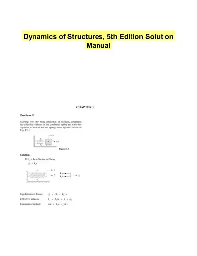 Textbook Guides
Dynamics of Structures, 5th Edition Solution Manual
Civil Engineering
603 pagesMay 2025 Textbook Guides
Solution Manual for Transportation Engineering and Planning, 3rd Edition
Civil Engineering
78 pages92downloadsFeb 2025 Textbook Guides
Reinforced Concrete Design, 9th Edition Solution Manual
Civil Engineering
198 pages65downloadsFeb 2025 Exam Guides
Principles Of Foundation Engineering, 8th Edition Test Bank
Civil Engineering
166 pages49downloadsFeb 2025 Textbook Guides
Structural Analysis, 10th Edition Solution Manual
Civil Engineering
716 pagesMay 2025 Textbook Guides
Solution Manual for Structural Steel Design, 6th Edition
Civil Engineering
511 pagesMay 2025 Past Exams
2023 CLC059 Construction Practice Exam With Answers (39 Solved Questions)
Civil Engineering
12 pagesMay 2025 Past Exams
The CE Shop Construction Final Exam With Answers (100 Solved Questions)
Civil Engineering
55 pagesMay 2025
Study this document with CramX
Once it is in your library, every tool can work from it.