

Mechanics of Materials, 10th Edition Solution Manual
- Mechanical Engineering
- 1569 pages
- Shared May 2025
Solve your textbook questions faster and more accurately with Mechanics of Materials, 10th Edition Solution Manual, a reliable guide for every chapter.
Preview 16 of 1569 pages
See the first 16 pages exactly as they appear in the document.
Page 1 Read page 1 as text
Solution 1 1–1. The shaft is supported by a smooth thrust bearing at B and a journal bearing at C . Determine the resultant internal loadings acting on the cross section at E . A E D B C 4 ft 400 lb 800 lb 4 ft 4 ft 4 ft Solution Support Reactions: We will only need to compute C y by writing the moment equation of equilibrium about B with reference to the free-body diagram of the entire shaft, Fig. a . a + Σ M B = 0; C y (8) + 400(4) - 800(12) = 0 C y = 1000 lb Internal Loadings: Using the result for C y , section DE of the shaft will be considered. Referring to the free-body diagram, Fig. b , S + Σ F x = 0; N E = 0 Ans. + c Σ F y = 0; V E + 1000 - 800 = 0 V E = - 200 lb Ans. a + Σ M E = 0; 1000(4) - 800(8) - M E = 0 M E = - 2400 lb # ft = - 2.40 kip # ft Ans. The negative signs indicates that V E and M E act in the opposite sense to that shown on the free-body diagram. Ans: N E = 0, V E = - 200 lb, M E = - 2.40 kip # ft
Page 2 Page 3 Read page 3 as text
Solution 2 1–2. Determine the resultant internal normal and shear force in the member at (a) section a – a and (b) section b – b , each of which passes through the centroid A . The 500-lb load is applied along the centroidal axis of the member. 30 ° A b a b a 500 lb 500 lb Solution (a) + S Σ F x = 0; N a - 500 = 0 N a = 500 lb Ans. + T Σ F y = 0; V a = 0 Ans. (b) R + Σ F x = 0; N b - 500 cos 30 ° = 0 N b = 433 lb Ans. + Q Σ F y = 0; V b - 500 sin 30 ° = 0 V b = 250 lb Ans. Ans: (a) N a = 500 lb, V a = 0, (b) N b = 433 lb, V b = 250 lb
Page 4 Read page 4 as text
Solution 3 1–3. Determine the resultant internal loadings acting on section b – b through the centroid C on the beam. 30 ° 6 ft 3 ft 60 ° b b 900 lb / ft C A B Solution Support Reaction: a + Σ M A = 0; N B (9 sin 30 ° ) - 1 2 (900)(9)(3) = 0 N B = 2700 lb Equations of Equilibrium: For section b–b S + Σ F x = 0; V b - b + 1 2 (300)(3) sin 30 ° - 2700 = 0 V b - b = 2475 lb = 2.475 kip Ans. + c Σ F y = 0; N b - b - 1 2 (300)(3) cos 30 ° = 0 N b - b = 389.7 lb = 0.390 kip Ans. a + Σ M C = 0; 2700(3 sin 30 ° ) - 1 2 (300)(3)(1) - M b - b = 0 M b - b = 3600 lb # ft = 3.60 kip # ft Ans. Ans: V b - b = 2.475 kip, N b - b = 0.390 kip, M b - b = 3.60 kip # ft
Page 5 Read page 5 as text
4 1–4. The shaft is supported by a smooth thrust bearing at A and a smooth journal bearing at B . Determine the resultant internal loadings acting on the cross section at C . A D B C 900 N 1.5 m 600 N / m 1.5 m 1 m 1 m 1 m Solution Support Reactions: We will only need to compute B y by writing the moment equation of equilibrium about A with reference to the free-body diagram of the entire shaft, Fig. a . a + Σ M A = 0; B y (4.5) - 600(2)(2) - 900(6) = 0 B y = 1733.33 N Internal Loadings: Using the result of B y , section CD of the shaft will be considered. Referring to the free-body diagram of this part, Fig. b , S + Σ F x = 0; N C = 0 Ans. + c Σ F y = 0; V C - 600(1) + 1733.33 - 900 = 0 V C = - 233 N Ans. a + Σ M C = 0; 1733.33(2.5) - 600(1)(0.5) - 900(4) - M C = 0 M C = 433 N # m Ans. The negative sign indicates that V C acts in the opposite sense to that shown on the free-body diagram. * Ans: N C = 0, V C = - 233 N, M C = 433 N # m
Page 6 Read page 6 as text
5 1–5. Determine the resultant internal loadings acting on the cross section at point B . A C 12 ft 3 ft 60 lb / ft B Solution S + Σ F x = 0; N B = 0 Ans. + c Σ F y = 0; V B - 1 2 (48)(12) = 0 V B = 288 lb Ans. a + Σ M B = 0; - M B - 1 2 (48)(12)(4) = 0 M B = - 1152 lb # ft = - 1.15 kip # ft Ans. Ans: N B = 0 V B = 288 lb, M B = - 1.15 kip # ft ,
Page 7 Read page 7 as text
6 1–6. Determine the resultant internal loadings on the cross section at point D . 2 m D 1.25 kN / m 1.5 m 1 m E B C A F 0.5 m 0.5 m 0.5 m Solution Support Reactions: Member BC is the two force member. a + Σ M A = 0; 4 5 F BC (1.5) - 1.875(0.75) = 0 F BC = 1.1719 kN + c Σ F y = 0; A y + 4 5 (1.1719) - 1.875 = 0 A y = 0.9375 kN S + Σ F x = 0; 3 5 (1.1719) - A x = 0 A x = 0.7031 kN Equations of Equilibrium: For point D S + Σ F x = 0; N D - 0.7031 = 0 N D = 0.703 kN Ans. + c Σ F y = 0; 0.9375 - 0.625 - V D = 0 V D = 0.3125 kN Ans. a + Σ M D = 0; M D + 0.625(0.25) - 0.9375(0.5) = 0 M D = 0.3125 kN # m Ans. Ans: N D = 0.703 kN, V D = 0.3125 kN, M D = 0.3125 kN # m
Page 8 Read page 8 as text
7 1–7. Determine the resultant internal loadings at cross sections at points E and F on the assembly. 2 m D 0.5 m 0.5 m 1.25 kN / m 0.5 m 1.5 m 1 m E B C A F Solution Support Reactions: Member BC is the two-force member. a + Σ M A = 0; 4 5 F BC (1.5) - 1.875(0.75) = 0 F BC = 1.1719 kN + c Σ F y = 0; A y + 4 5 (1.1719) - 1.875 = 0 A y = 0.9375 kN S + Σ F x = 0; 3 5 (1.1719) - A x = 0 A x = 0.7031 kN Equations of Equilibrium: For point F + b Σ F x ′ = 0; N F - 1.1719 = 0 N F = 1.17 kN Ans. a + Σ F y ′ = 0; V F = 0 Ans. a + Σ M F = 0; M F = 0 Ans. Equations of Equilibrium: For point E + d Σ F x = 0; N E - 3 5 (1.1719) = 0 N E = 0.703 kN Ans. + c Σ F y = 0; V E - 0.625 + 4 5 (1.1719) = 0 V E = - 0.3125 kN Ans. a + Σ M E = 0; - M E - 0.625(0.25) + 4 5 (1.1719)(0.5) = 0 M E = 0.3125 kN # m Ans. Negative sign indicates that V E acts in the opposite direction to that shown on FBD. Ans: N F = 1.17 kN, V F = 0, M F = 0, N E = 0.703 kN, V E = - 0.3125 kN, M E = 0.3125 kN # m
Page 9 Read page 9 as text
8 * 1–8. The beam supports the distributed load shown. Determine the resultant internal loadings acting on the cross section at point C . Assume the reactions at the supports A and B are vertical. 1.5 m 3 m D C A B 4 kN / m 1.5 m Solution Support Reactions: Referring to the FBD of the entire beam, Fig. a , a + Σ M A = 0; B y (6) - 1 2 (4)(6)(2) = 0 B y = 4.00 kN Internal Loadings: Referring to the FBD of the right segment of the beam sectioned through C , Fig. b , S + Σ F x = 0; N C = 0 Ans. + c Σ F y = 0; V C + 4.00 - 1 2 (3)(4.5) = 0 V C = 2.75 kN Ans. a + Σ M C = 0; 4.00(4.5) - 1 2 (3)(4.5)(1.5) - M C = 0 M C = 7.875 kN # m Ans. Ans: N C = 0, V C = 2.75 kN, M C = 7.875 kN # m
Page 10 Read page 10 as text
9 1–9. The beam supports the distributed load shown. Determine the resultant internal loadings acting on the cross section at point D . Assume the reactions at the supports A and B are vertical. 1.5 m 3 m D C A B 4 kN / m 1.5 m Solution Support Reactions: Referring to the FBD of the entire beam, Fig. a , a + Σ M A = 0; B y (6) - 1 2 (4)(6)(2) = 0 B y = 4.00 kN Internal Loadings: Referring to the FBD of the right segment of the beam sectioned through D , Fig. b , S + Σ F x = 0; N D = 0 Ans. + c Σ F y = 0; V D + 4.00 - 1 2 (1.00)(1.5) = 0 V D = - 3.25 kN Ans. a + Σ M D = 0; 4.00(1.5) - 1 2 (1.00)(1.5)(0.5) - M D = 0 M D = 5.625 kN # m Ans. The negative sign indicates that V D acts in the sense opposite to that shown on the FBD. Ans: N D = 0, V D = - 3.25 kN, M D = 5.625 kN # m
Page 11 Read page 11 as text
10 1–10. The boom DF of the jib crane and the column DE have a uniform weight of 50 lb / ft. If the supported load is 300 lb, determine the resultant internal loadings in the crane on cross sections at points A , B , and C . 5 ft 7 ft C D F E B A 300 lb 2 ft 8 ft 3 ft Solution Equations of Equilibrium: For point A d + Σ F x = 0; N A = 0 Ans. + c Σ F y = 0; V A - 150 - 300 = 0 V A = 450 lb Ans. a + Σ M A = 0; - M A - 150(1.5) - 300(3) = 0 M A = - 1125 lb # ft = - 1.125 kip # ft Ans. Negative sign indicates that M A acts in the opposite direction to that shown on FBD. Equations of Equilibrium: For point B d + Σ F x = 0; N B = 0 Ans. + c Σ F y = 0; V B - 550 - 300 = 0 V B = 850 lb Ans. a + Σ M B = 0; - M B - 550(5.5) - 300(11) = 0 M B = - 6325 lb # ft = - 6.325 kip # ft Ans. Negative sign indicates that M B acts in the opposite direction to that shown on FBD. Equations of Equilibrium: For point C d + Σ F x = 0; V C = 0 Ans. + c Σ F y = 0; - N C - 250 - 650 - 300 = 0 N C = - 1200 lb = - 1.20 kip Ans. a + Σ M C = 0; - M C - 650(6.5) - 300(13) = 0 M C = - 8125 lb # ft = - 8.125 kip # ft Ans. Negative signs indicate that N C and M C act in the opposite direction to that shown on FBD. Ans: N A = 0, V A = 450 lb, M A = - 1.125 kip # ft, N B = 0, V B = 850 lb, M B = - 6.325 kip ft, # V C = 0, N C = - 1.20 kip, M C = - 8.125 kip # ft
Page 12 Read page 12 as text
11 1–11. Determine the resultant internal loadings acting on the cross sections at points D and E of the frame. 4 ft A D 2 ft C B 75 lb / ft 1 ft 150 lb 1 ft E 30 ° 2 ft 1 ft G 1 ft F Solution Member AG : a + Σ M A = 0; 4 5 F BC (3) - 75(4)(5) - 150 cos 30 ° (7) = 0; F BC = 1003.89 lb a + Σ M B = 0; A y (3) - 75(4)(2) - 150 cos 30 ° (4) = 0; A y = 373.20 lb S + Σ F x = 0; A x - 3 5 (1003.89) + 150 sin 30 ° = 0; A x = 527.33 lb For point D : S + Σ F x = 0; N D + 527.33 = 0 N D = - 527 lb Ans. + c Σ F y = 0; - 373.20 - V D = 0 V D = - 373 lb Ans. a + Σ M D = 0; M D + 373.20(1) = 0 M D = - 373 lb # ft Ans. For point E : S + Σ F x = 0; 150 sin 30 ° - N E = 0 N E = 75.0 lb Ans. + c Σ F y = 0; V E - 75(3) - 150 cos 30 ° = 0 V E = 355 lb Ans. a + Σ M E = 0; - M E - 75(3)(1.5) - 150 cos 30 ° (3) = 0; M E = - 727 lb # ft Ans. Ans: N D = - 527 lb, V D = - 373 lb, M D = - 373 lb ft, # N E = 75.0 lb, V E = 355 lb , M E = - 727 lb # ft
Page 13 Read page 13 as text
12 1–12. Determine the resultant internal loadings acting on the cross sections at points F and G of the frame. 4 ft A D 2 ft C B 75 lb / ft 1 ft 150 lb 1 ft E 30 ° 2 ft 1 ft G 1 ft F Solution Member AG : a + Σ M A = 0; 4 5 F BF (3) - 300(5) - 150 cos 30 ° (7) = 0 F BF = 1003.9 lb For point F : + Q Σ F x ′ = 0; V F = 0 Ans. a + Σ F y ′ = 0; N F - 1003.9 = 0 N F = 1004 lb Ans. a + Σ M F = 0; M F = 0 Ans. For point G : d + Σ F x = 0; N G - 150 sin 30 ° = 0 N G = 75.0 lb Ans. + c Σ F y = 0; V G - 75(1) - 150 cos 30 ° = 0 V G = 205 lb Ans. a + Σ M G = 0; - M G - 75(1)(0.5) - 150 cos 30 ° (1) = 0 M G = - 167 lb # ft Ans. * Ans: V F = 0, N F = 1004 lb, M F = 0 , N G = 75.0 lb, V G = 205 lb, M G = - 167 lb # ft
Page 14 Read page 14 as text
13 1–13. The blade of the hacksaw is subjected to a pretension force of F = 100 N. Determine the resultant internal loadings acting on section a – a that passes through point D . A B C D F F a b b a 30 ° 225 mm 150 mm E Solution Internal Loadings: Referring to the free-body diagram of the section of the hacksaw shown in Fig. a , d + Σ F x = 0; N a - a + 100 = 0 N a - a = - 100 N Ans. + c Σ F y = 0; V a - a = 0 Ans. a + Σ M D = 0; - M a - a - 100(0.15) = 0 M a - a = - 15 N m # Ans. The negative sign indicates that N a - a and M a - a act in the opposite sense to that shown on the free-body diagram. Ans: N a - a = - 100 N, V a - a = 0, M a - a = - 15 N # m
Page 15 Read page 15 as text
14 1–14. The blade of the hacksaw is subjected to a pretension force of F = 100 N. Determine the resultant internal loadings acting on section b – b that passes through point D . A B C D F F a b b a 30 ° 225 mm 150 mm E Solution Internal Loadings: Referring to the free-body diagram of the section of the hacksaw shown in Fig. a , Σ F x ′ = 0; N b - b + 100 cos 30 ° = 0 N b - b = - 86.6 N Ans. Σ F y ′ = 0; V b - b - 100 sin 30 ° = 0 V b - b = 50 N Ans. a + Σ M D = 0; - M b - b - 100(0.15) = 0 M b - b = - 15 N # m Ans. The negative sign indicates that N b – b and M b – b act in the opposite sense to that shown on the free-body diagram. Ans: N b - b = - 86.6 N, V b - b = 50 N, M b - b = - 15 N # m
Page 16 Read page 16 as text
15 1–15. The beam supports the triangular distributed load shown. Determine the resultant internal loadings on the cross section at point C . Assume the reactions at the supports A and B are vertical. 6 ft 6 ft C A B 4.5 ft 800 lb / ft 6 ft 4.5 ft E D Solution Support Reactions: Referring to the FBD of the entire beam, Fig. a , a + Σ M B = 0; 1 2 (0.8)(18)(6) - 1 2 (0.8)(9)(3) - A y (18) = 0 A y = 1.80 kip Internal Loadings: Referring to the FBD of the left beam segment sectioned through point C , Fig. b , S + Σ F x = 0; N C = 0 Ans. + c Σ F y = 0; 1.80 - 1 2 (0.5333)(12) - V C = 0 V C = - 1.40 kip Ans. a + Σ M C = 0; M C + 1 2 (0.5333)(12)(4) - 1.80(12) = 0 M C = 8.80 kip # ft Ans. The negative sign indicates that V C acts in the sense opposite to that shown on the FBD. Ans: N C = 0, V C = - 1.40 kip, M C = 8.80 kip # ft
1553 more pages in the full document
Unlock it once and it stays in your library, ready to chat with or turn into flashcards.
Unlock the full documentMore Mechanical Engineering study materials
See all Textbook Guides
Solution Manual for Engineering Mechanics Dynamics, 13th Edition
Mechanical Engineering
1360 pages123downloadsFeb 2025 Textbook Guides
Solution Manual For Introduction To Engineering Experimentation, 3rd Edition
Mechanical Engineering
298 pages99downloadsFeb 2025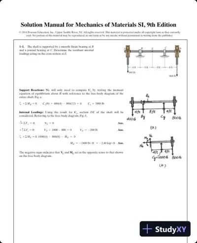 Textbook Guides
Solution Manual for Mechanics of Materials SI, 9th Edition
Mechanical Engineering
1598 pages91downloadsFeb 2025 Textbook Guides
Solution Manual for Engineering Mechanics: Dynamics, 2nd Edition
Mechanical Engineering
41 pages82downloadsFeb 2025 Textbook Guides
Solution Manual for Finite Element Analysis: Theory and Application with ANSYS, 5th Edition
Mechanical Engineering
426 pages53downloadsFeb 2025 Textbook Guides
Solution Manual For Modern Compressible Flow: With Historical Perspective, 3rd Edition
Mechanical Engineering
362 pages52downloadsFeb 2025 Certification Guides
Biofluid Mechanics: An Introduction to Fluid Mechanics, Macrocirculation, and Microcirculation, 3rd Edition (2021)
Mechanical Engineering
172 pages48downloadsFeb 2025 Textbook Guides
Solution Manual for Introduction to Finite Elements in Engineering, 4th Edition
Mechanical Engineering
308 pages47downloadsFeb 2025
Study this document with CramX
Once it is in your library, every tool can work from it.