Solution Manual for Mechanics of Materials SI, 9th Edition

Solve textbook problems faster with Solution Manual for Mechanics of Materials SI, 9th Edition, a must-have for every student.

Andrew Taylor
Contributor
4.7
91
about 1 year ago
Preview (31 of 1598 Pages)
100%
Log in to unlock

Page 1

Solution Manual for Mechanics of Materials SI, 9th Edition - Page 1 preview image

Loading page ...

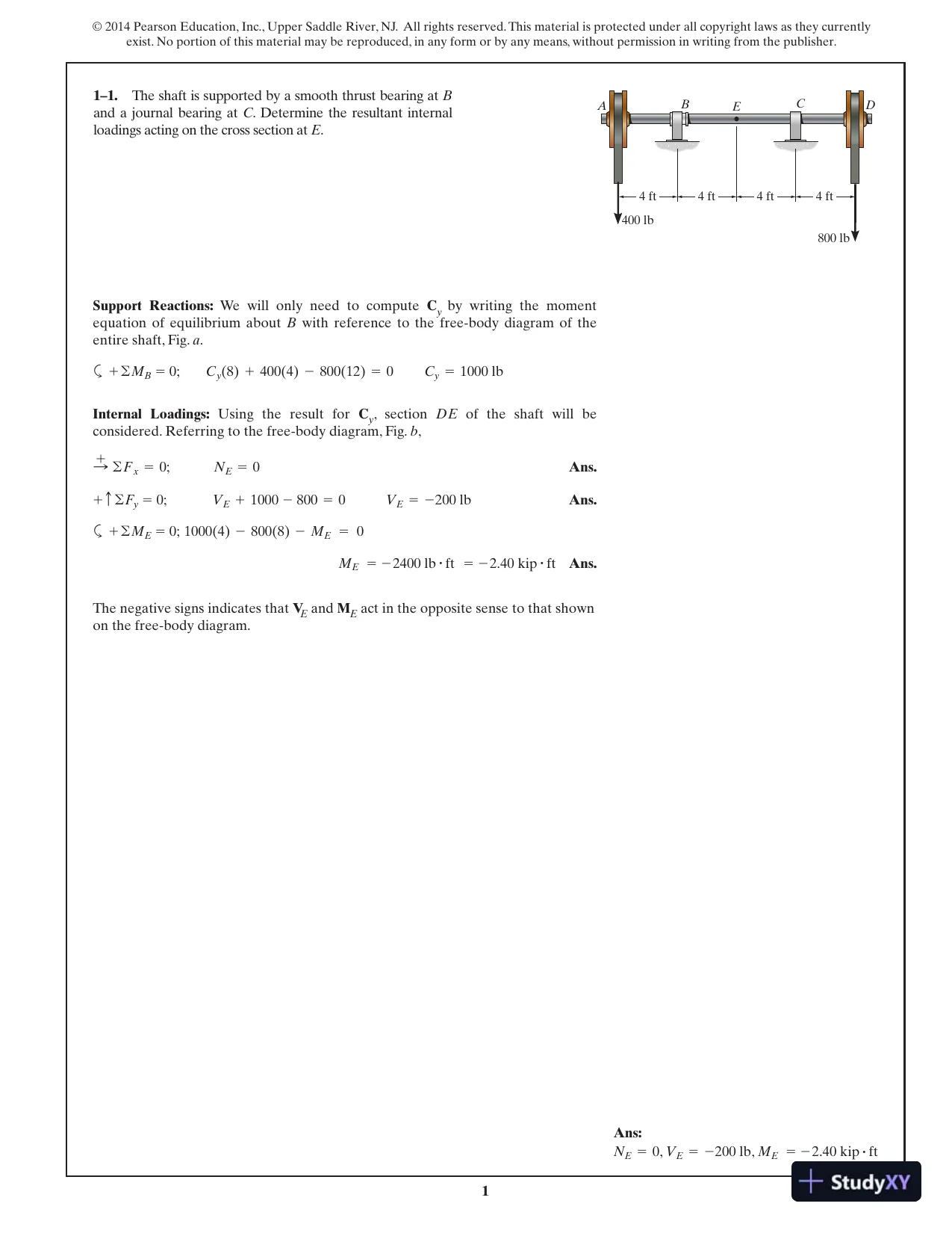
11–1.The shaft is supported by a smooth thrust bearing atBand a journal bearing atC. Determine the resultant internalloadings acting on the cross section atE.Support Reactions:We will only need to computeCyby writing the momentequation of equilibrium aboutBwith reference to the free-body diagram of theentire shaft, Fig.a.aInternal Loadings:Using the result forCy, sectionDEof the shaft will beconsidered. Referring to the free-body diagram, Fig.b,Ans.Ans.aAns.The negative signs indicates thatVEandMEact in the opposite sense to that shownon the free-body diagram.ME= -2400 lb#ft= -2.40 kip#ft1000(4)-800(8)-ME=0+ ©ME=0;VE= -200 lbVE+1000-800=0+ c ©Fy=0;NE=0:+ ©Fx=0;Cy=1000 lbCy(8)+400(4)-800(12)=0+ ©MB=0;AEDBC4 ft400 lb800 lb4 ft4 ft4 ftAns:,,ME= -2.40 kip#ftVE= -200 lbNE=0

Page 2

Solution Manual for Mechanics of Materials SI, 9th Edition - Page 2 preview image

Loading page ...

Page 3

Solution Manual for Mechanics of Materials SI, 9th Edition - Page 3 preview image

Loading page ...

21–2.Determine the resultant internal normal and shearforce in the member at (a) sectiona–aand (b) sectionb–b,each of which passes through pointA. The 500-lb load isapplied along the centroidal axis of the member.(a)Ans.Ans.(b)Ans.Ans.Vb=250 lbVb-500 sin 30°=0+Fy=0;Nb=433 lbNb-500 cos 30°=0R+ ©Fx=0;Va=0+ T©Fy=0;Na=500 lbNa-500=0:+ ©Fx=0;30Ababa500 lb500 lbAns:,,Vb=250 lbNb=433 lb,Va=0Na=500 lb

Page 4

Solution Manual for Mechanics of Materials SI, 9th Edition - Page 4 preview image

Loading page ...

31–3.The beamABis fixed to the wall and has a uniformweight of 80 lb ft. If the trolley supports a load of 1500 lb,determine the resultant internal loadings acting on the crosssections through pointsCandD.>SegmentBC:Ans.Ans.aAns.SegmentBD:Ans.Ans.aAns.MD= -0.360 kip#ft-MD-0.24(1.5)=0+ ©MD=0;VD=0.240 kipVD-0.24=0+ c ©Fy=0;ND=0;+ ©Fx=0;MC= -47.5 kip#ft-MC-2(12.5)-1.5(15)=0+ ©MC=0;VC=3.50 kipVC-2.0-1.5=0+ c©Fy=0;NC=0;+ ©Fx=0;D5 ft20 ft3 ft10 ftCBA1500 lbAns:,,,,MD= -0.360 kip#ftVD=0.240 kipND=0MC= -47.5 kip#ft,VC=3.50 kipNC=0

Page 5

Solution Manual for Mechanics of Materials SI, 9th Edition - Page 5 preview image

Loading page ...

4*1–4.The shaft is supported by a smooth thrust bearing atAand a smooth journal bearing atB. Determine the resultantinternal loadings acting on the cross section atC.Support Reactions:We will only need to computeByby writing the momentequation of equilibrium aboutAwith reference to the free-body diagram of theentire shaft, Fig.a.aInternalLoadings:UsingtheresultofBy, sectionCDoftheshaftwillbeconsidered. Referring to the free-body diagram of this part, Fig.b,Ans.Ans.aAns.The negative sign indicates thatVCact in the opposite sense to that shown on thefree-body diagram.MC=433 N#m1733.33(2.5)-600(1)(0.5)-900(4)-MC=0+ ©MC=0;VC= -233 NVC-600(1)+1733.33-900=0+ c©Fy=0;NC=0;+ ©Fx=0;By=1733.33 NBy(4.5)-600(2)(2)-900(6)=0+ ©MA=0;ADBC900 N1.5 m600 N/m1.5 m1 m1 m1 m

Page 6

Solution Manual for Mechanics of Materials SI, 9th Edition - Page 6 preview image

Loading page ...

51–5.Determinetheresultantinternalloadingsinthebeam at cross sections through pointsDandE. PointEisjust to the right of the 3-kip load.Support Reactions:For memberABaEquations of Equilibrium:For pointDAns.Ans.aAns.Equations of Equilibrium:For pointEAns.Ans.aAns.Negative signs indicate thatMEandVEact in the opposite direction to that shownon FBD.ME= -24.0 kip#ft+ ©ME=0;ME+6.00(4)=0VE= -9.00 kip+ c ©Fy=0;-6.00-3-VE=0:+ ©Fx=0;NE=0MD=13.5 kip#ft+ ©MD=0;MD+2.25(2)-3.00(6)=0VD=0.750 kip+ c ©Fy=0;3.00-2.25-VD=0:+©Fx=0;ND=0+ c ©Fy=0;By+3.00-9.00=0By=6.00 kip:+ ©Fx=0;Bx=0+ ©MB=0;9.00(4)-Ay(12)=0Ay=3.00 kip6 ft4 ftA4 ftBCDE6 ft3 kip1.5 kip/ftAns:,,,,ME= -24.0 kip#ftVE= -9.00 kipNE=0MD=13.5 kip#ft,VD=0.750 kipND=0

Page 7

Solution Manual for Mechanics of Materials SI, 9th Edition - Page 7 preview image

Loading page ...

61–6.Determinethenormalforce,shearforce,andmoment at a section through pointC. TakeP=8 kN.Support Reactions:aEquations of Equilibrium:For pointCAns.Ans.aAns.Negative signs indicate thatNCandVCact in the opposite direction to that shownon FBD.MC=6.00 kN#m+ ©MC=0;8.00(0.75)-MC=0VC= -8.00 kN+ c ©Fy=0;VC+8.00=0NC= -30.0 kN:+ ©Fx=0;-NC-30.0=0+ c ©Fy=0;Ay-8=0Ay=8.00 kN:+ ©Fx=0;30.0-Ax=0Ax=30.0 kN+ ©MA=0;8(2.25)-T(0.6)=0T=30.0 kN0.75 mCPAB0.5 m0.1 m0.75 m0.75 mAns:MC=6.00 kN#mVC= -8.00 kN,NC= -30.0 kN,

Page 8

Solution Manual for Mechanics of Materials SI, 9th Edition - Page 8 preview image

Loading page ...

7Support Reactions:aAns.Equations of Equilibrium:For pointCAns.Ans.aAns.Negative signs indicate thatNCandVCact in the opposite direction to that shownon FBD.MC=0.400 kN#m+ ©MC=0;0.5333(0.75)-MC=0VC= -0.533 kN+ c ©Fy=0;VC+0.5333=0NC= -2.00 kN:+ ©Fx=0;-NC-2.00=0+ c ©Fy=0;Ay-0.5333=0Ay=0.5333 kN:+ ©Fx=0;2-Ax=0Ax=2.00 kNP=0.5333 kN=0.533 kN+ ©MA=0;P(2.25)-2(0.6)=01–7.The cable will fail when subjected to a tension of 2 kN.Determine the largest vertical loadPthe frame will supportand calculate the internal normal force, shear force, andmoment at the cross section through pointCfor this loading.0.75 mCPAB0.5 m0.1 m0.75 m0.75 mAns:,,,MC=0.400 kN#mVC= -0.533 kNNC= -2.00 kNP=0.533 kN

Page 9

Solution Manual for Mechanics of Materials SI, 9th Edition - Page 9 preview image

Loading page ...

8Referring to the FBD of the entire beam, Fig.a,aReferring to the FBD of this segment, Fig.b,Ans.Ans.aAns.+ ©MC=0;MC+6(0.5)-7.5(1)=0MC=4.50 kN#m+ c ©Fy=0;7.50-6-VC=0VC=1.50 kN:+ ©Fx=0;NC=0+ ©MB=0;-Ay(4)+6(3.5)+12 (3)(3)(2)=0Ay=7.50 kN*1–8.Determine the resultant internal loadings on thecross section through pointC. Assume the reactions at thesupportsAandBare vertical.0.5 m 0.5 m1.5 m1.5 mCAB3 kN/m6 kND

Page 10

Solution Manual for Mechanics of Materials SI, 9th Edition - Page 10 preview image

Loading page ...

9Referring to the FBD of the entire beam, Fig.a,aReferring to the FBD of this segment, Fig.b,Ans.Ans.aAns.=3.94 kN#m+ ©MD=0;3.00(1.5)-12 (1.5)(1.5)(0.5)-MD=0MD=3.9375 kN#m+ c ©Fy=0;VD-12 (1.5)(1.5)+3.00=0VD= -1.875 kN:+ ©Fx=0;ND=0+ ©MA=0;By(4)-6(0.5)-12 (3)(3)(2)=0By=3.00 kN1–9.Determine the resultant internal loadings on thecross section through pointD. Assume the reactions at thesupportsAandBare vertical.Ans:MD=3.94 kN#mND=0,VD= -1.875 kN,0.5 m 0.5 m1.5 m1.5 mCAB3 kN/m6 kND

Page 11

Solution Manual for Mechanics of Materials SI, 9th Edition - Page 11 preview image

Loading page ...

10Equations of Equilibrium:For pointAAns.Ans.aAns.Negative sign indicates thatMAacts in the opposite direction to that shown on FBD.Equations of Equilibrium:For pointBAns.Ans.aAns.Negative sign indicates thatMBacts in the opposite direction to that shown on FBD.Equations of Equilibrium:For pointCAns.Ans.aAns.Negative signs indicate thatNCandMCact in the opposite direction to that shownon FBD.MC= -8125 lb#ft= -8.125 kip#ft+ ©MC=0;-MC-650(6.5)-300(13)=0NC= -1200 lb= -1.20 kip+ c ©Fy=0;-NC-250-650-300=0;+ ©Fx=0;VC=0MB= -6325 lb#ft= -6.325 kip#ft+ ©MB=0;-MB-550(5.5)-300(11)=0VB=850 lb+ c ©Fy=0;VB-550-300=0;+ ©Fx=0;NB=0MA= -1125 lb#ft= -1.125 kip#ft+ ©MA=0;-MA-150(1.5)-300(3)=0VA=450 lb+ c ©Fy=0;VA-150-300=0;+ ©Fx=0;NA=01–10.The boomDFof the jib crane and the columnDEhave a uniform weight of 50 lb ft. If the hoist and loadweigh 300 lb, determine the resultant internal loadings inthe crane on cross sections through pointsA,B, andC.>5 ft7 ftCDFEBA300 lb2 ft8 ft3 ftAns:,,,,,MC= -8.125 kip#ftNC= -1.20 kip,VC=0MB= -6.325 kip#ft,VB=850 lbNB=0MA= -1.125 kip#ft,VA=450 lbNA=0

Page 12

Solution Manual for Mechanics of Materials SI, 9th Edition - Page 12 preview image

Loading page ...

111–11.The forearm and biceps support the 2-kg load atA. IfCcan be assumed as a pin support, determine the resultantinternal loadings acting on the cross section of the bone of theforearm atE.The biceps pulls on the bone alongBD.Support Reactions:In this case, all the support reactions will be completed.Referring to the free-body diagram of the forearm, Fig.a,aInternal Loadings:Using the results ofCxandCy, sectionCEof the forearm will beconsidered. Referring to the free-body diagram of this part shown in Fig.b,Ans.Ans.aAns.The negative signs indicate thatNE,VEandMEact in the opposite sense to thatshown on the free-body diagram.ME= -2.26 N#mME+64.47(0.035)=0+ ©ME=0;VE= -64.5 N-VE-64.47=0+ c©Fy=0;NE= -22.5 NNE+22.53=0:+ ©Fx=0;Cy=64.47 N87.05 sin 75°-2(9.81)-Cy=0+ c ©Fy=0;Cx=22.53 NCx-87.05 cos 75°=0:+ ©Fx=0;FBD=87.05NFBDsin 75°(0.07)-2(9.81)(0.3)=0+ ©MC=0;75230 mm35 mm35 mmCE BDAAns:,,ME= -2.26 N#mVE= -64.5 NNE= -22.5 N

Page 13

Solution Manual for Mechanics of Materials SI, 9th Edition - Page 13 preview image

Loading page ...

12*1–12.The serving trayTused on an airplane is supportedoneach sideby an arm. The tray is pin connected to the armatA, and atBthere is a smooth pin. (The pin can movewithin the slot in the arms to permit folding the tray againstthe front passenger seat when not in use.) Determine theresultant internal loadings acting on the cross section of thearm through pointCwhen the tray arm supports the loadsshown.Ans.Ans.aAns.MC= -9.46 N#m+ ©MC=0;-MC-9(0.5 cos 60°+0.115)-12(0.5 cos 60°+0.265)=0VC=10.5 NVC-9 sin 30°-12 sin 30°=0;a+ ©Fy=0;NC= -18.2 NNC+9 cos 30°+12 cos 30°=0;b+ ©Fx=0;9 N500 mm12 N15 mm150 mm60ABCTVCMCNC100 mm

Page 14

Solution Manual for Mechanics of Materials SI, 9th Edition - Page 14 preview image

Loading page ...

13Internal Loadings:Referring to the free-body diagram of the section of the hacksawshown in Fig.a,Ans.Ans.aAns.The negative sign indicates thatNa–aandMa–aact in the opposite sense to thatshown on the free-body diagram.Ma-a= -15 N#m-Ma-a-100(0.15)=0+ ©MD=0;Va-a=0+ c ©Fy=0;Na-a= -100 NNa-a+100=0;+ ©Fx=0;1–13.Thebladeofthehacksawissubjectedtoapretension force ofDetermine the resultantinternal loadings acting on sectiona–athat passes throughpointD.F=100 N.ABCDFFabba30225 mm150 mmAns:,,Ma-a= -15 N#mVa-a=0Na-a= -100 N

Page 15

Solution Manual for Mechanics of Materials SI, 9th Edition - Page 15 preview image

Loading page ...

141–14.Thebladeofthehacksawissubjectedtoapretension force of. Determine the resultantinternal loadings acting on sectionb–bthat passes throughpointD.F=100 NInternal Loadings:Referring to the free-body diagram of the section of the hacksawshown in Fig.a,Ans.Ans.aAns.The negative sign indicates thatNb–bandMb–bact in the opposite sense to thatshown on the free-body diagram.Mb-b= -15 N#m-Mb-b-100(0.15)=0+ ©MD=0;Vb-b=50 N©Fy¿=0;Vb-b-100 sin 30°=0Nb-b= -86.6 N©Fx¿=0;Nb-b+100 cos 30°=0ABCDFFabba30225 mm150 mmAns:,,Mb-b= -15 N#mVb-b=50 NNb-b= -86.6 N

Page 16

Solution Manual for Mechanics of Materials SI, 9th Edition - Page 16 preview image

Loading page ...

151–15.A 150-lb bucket is suspended from a cable on thewooden frame. Determine the resultant internal loadingson the cross section atD.Support Reactions:We will only need to computeBx,By, andFGH. Referring to thefree-body diagram of memberBC,Fig.a,aInternal Loadings:Using the results ofBxandBy, sectionBDof memberBCwill beconsidered. Referring to the free-body diagram of this part shown in Fig.b,Ans.Ans.aAns.The negative signs indicates thatVDandMDact in the opposite sense to that shownon the free-body diagram.MD= -150 lb#ft150(1)+MD=0+ ©MD=0;VD= -150 lb-VD-150=0+ c ©Fy=0;ND=300 lbND-300=0:+ ©Fx=0;By=150 lb424.26 sin 45°-150-By=0+ c©Fy=0;Bx=300 lb424.26 cos 45°-Bx=0:+ ©Fx=0;FGH=424.26 lbFGHsin 45°(2)-150(4)=0+ ©MB=0:2 ft2 ft3 ft1 ft1 ft1 ftEDCBAI30GHAns:,,MD= -150 lb#ftVD= -150 lbND=300 lb

Page 17

Solution Manual for Mechanics of Materials SI, 9th Edition - Page 17 preview image

Loading page ...

16*1–16.A 150-lb bucket is suspended from a cable on thewooden frame. Determine the resultant internal loadingsacting on the cross section atE.Support Reactions:We will only need to computeAx,Ay, andFBI. Referring to thefree-body diagram of the frame, Fig.a,aInternal Loadings:Using the results ofAxandAy, sectionAEof memberABwill beconsidered. Referring to the free-body diagram of this part shown in Fig.b,Ans.Ans.aAns.The negative sign indicates thatNEacts in the opposite sense to that shown on thefree-body diagram.ME=300 lb#ft100(3)-ME=0+ ©MD=0;VE=100 lb100-VE=0+ c ©Fy=0;NE= -323 lbNE+323.21=0:+ ©Fx=0;Ay=323.21 lbAy-200 cos 30°-150=0+ c ©Fy=0;Ax=100 lbAx-200 sin 30°=0:+ ©Fx=0;FBI=200 lbFBIsin 30°(6)-150(4)=0+ ©MA=0;2 ft2 ft3 ft1 ft1 ft1 ftEDCBAI30GH

Page 18

Solution Manual for Mechanics of Materials SI, 9th Edition - Page 18 preview image

Loading page ...

17451.5 m1.5 m3 m45ACBbaab5 kNReferring to the FBD of the entire beam, Fig.a,aReferring to the FBD of this segment (sectiona–a), Fig.b,Ans.Ans.aAns.Referring to the FBD (sectionb–b) in Fig.c,Ans.Ans.aAns.Mb-b=3.75 kN#m+ ©MC=0;5.303 sin 45° (3)-5(1.5)-Mb-b=0+ c ©Fy=0;Vb-b-5 sin 45°=0Vb-b=3.536 kN=3.54 kN= -1.77 kN;+ ©Fx=0;Nb-b-5 cos 45°+5.303=0Nb-b= -1.768 kN+©MC=0;5.303 sin 45°(3)-5(1.5)-Ma-a=0Ma-a=3.75 kN#m+a©Fy¿=0;Va-a+5.303 sin 45°-5=0Va-a=1.25 kN+b©Fx¿=0;Na-a+5.303 cos 45°=0Na-a= -3.75 kN+©MA=0;NBsin 45°(6)-5(4.5)=0NB=5.303 kN1–17.Determineresultantinternalloadingsactingonsectiona–aand sectionb–b. Each section passes throughthe centerline at pointC.Ans:Mb-b=3.75 kN#mVb-b=3.54 kN#m,Nb-b= -1.77 kN,Ma-a=3.75 kN#m,Va-a=1.25 kN,Na-a= -3.75 kN,

Page 19

Solution Manual for Mechanics of Materials SI, 9th Edition - Page 19 preview image

Loading page ...

18SegmentAC:Ans.Ans.aAns.+ ©MC=0;MC+80(6)=0;MC= -480 lb#in.+ c©Fy=0;VC=0:+ ©Fx=0;NC+80=0;NC= -80 lb1–18.The bolt shank is subjected to a tension of 80 lb.Determine the resultant internal loadings acting on thecross section at pointC.ABC906 in.Ans:MC= -480 lb#in.VC=0,NC= -80 lb,

Page 20

Solution Manual for Mechanics of Materials SI, 9th Edition - Page 20 preview image

Loading page ...

19Referring to the FBD of the entire beam, Fig.a,aReferring to the FBD of this segment, Fig.b,Ans.Ans.aAns.MC=31.5 kip#ft+ ©MC=0;MC+(3)(3)(1.5)+12 (3)(3)(2)-18.0(3)=0+ c ©Fy=0;18.0-12 (3)(3)-(3)(3)-VC=0VC=4.50 kip:+ ©Fx=0;NC=0+ ©MB=0;12 (6)(6)(2)+12 (6)(6)(10)-Ay(12)=0Ay=18.0 kip1–19.Determine the resultant internal loadings acting onthe cross section through pointC. Assume the reactions atthe supportsAandBare vertical.3 ft3 ftDCAB6 ft6 kip/ft6 kip/ftAns:,,MC=31.5 kip#ftVC=4.50 kipNC=0

Page 21

Solution Manual for Mechanics of Materials SI, 9th Edition - Page 21 preview image

Loading page ...

20Referring to the FBD of the entire beam, Fig.a,aReferring to the FBD of this segment, Fig.b,Ans.Ans.aAns.+ ©MA=0;MD-18.0 (2)=0MD=36.0 kip#ft+ c ©Fy=0;18.0-12 (6)(6)-VD=0VD=0:+ ©Fx=0;ND=0+ ©MB=0;12 (6)(6)(2)+12 (6)(6)(10)-Ay(12)=0Ay=18.0 kip*1–20.Determine the resultant internal loadings actingon the cross section through pointD. Assume the reactionsat the supportsAandBare vertical.3 ft3 ftDCAB6 ft6 kip/ft6 kip/ft

Page 22

Solution Manual for Mechanics of Materials SI, 9th Edition - Page 22 preview image

Loading page ...

21Internal Loadings:Referring to the free-body diagram of the section of the clampshown in Fig.a,Ans.Ans.aAns.+ ©MA=0;900(0.2)-Ma-a=0Ma-a=180 N#m©Fx¿=0;Va-a-900 sin 30°=0Va-a=450 N©Fy¿=0;900 cos 30°-Na-a=0Na-a=779 N1–21.The forged steel clamp exerts a force ofNon the wooden block. Determine the resultant internalloadings acting on sectiona–apassing through pointA.F=900200 mmaaF900 NF900 N30AAns:Ma-a=180 N#m:Va-a=450 N,Na-a=779 N,

Page 23

Solution Manual for Mechanics of Materials SI, 9th Edition - Page 23 preview image

Loading page ...

221–22.The metal stud punch is subjected to a force of 120 Non the handle. Determine the magnitude of the reactive forceat the pinAand in the short linkBC. Also, determine theinternal resultant loadings acting on the cross section passingthrough the handle arm atD.Member:aAns.Ans.Segment:Ans.Ans.aAns.MD=36.0 N#mMD-120(0.3)=0+ ©MD=0;VD=0+Fy¿=0;ND=120 NND-120=0a+ ©Fx¿=0;=1.49 kN=1491 NFA=21489.562+602Ax=60 NAx-120 sin 30°=0;;+ ©Fx=0;Ay=1489.56 NAy-1385.6-120 cos 30°=0+ c ©Fy=0;FBC=1385.6 N=1.39 kNFBCcos 30°(50)-120(500)=0MA=0;6050 mm100 mm200 mm300 mmBCD120 N50 mm100 mmE30AAns:,,MD=36.0 N#mVD=0,ND=120 N,FA=1.49 kNFBC=1.39 kN

Page 24

Solution Manual for Mechanics of Materials SI, 9th Edition - Page 24 preview image

Loading page ...

231–23.Solve Prob. 1–22 for the resultant internal loadingsacting on the cross section passing through the handle armatEand at a cross section of the short linkBC.Member:aSegment:Ans.Ans.aAns.Short link:Ans.Ans.aAns.M=0+ ©MH=0;N=1.39 kN1.3856-N=0;+ c ©Fy=0;V=0;+ ©Fx=0;ME=48.0 N#mME-120(0.4)=0;+ ©ME=0;VE=120 NVE-120=0;a+ ©Fy¿=0;NE=0+Fx¿=0;FBC=1385.6 N=1.3856 kNFBCcos 30°(50)-120(500)=0+©MA=0;6050 mm100 mm200 mm300 mmBCD120 N50 mm100 mmE30AAns:,,Short link:M=0N=1.39 kN,V=0,ME=48.0 N#m,VE=120 NNE=0

Page 25

Solution Manual for Mechanics of Materials SI, 9th Edition - Page 25 preview image

Loading page ...

24*1–24.Determine the resultant internal loadings actingon the cross section of the semicircular arch atC.aByAns.Ans.aAns.MC=0w0r(r)-MC+(-w0r)(r)=0+ ©M0=0;V2=0w0r+VC-w0r(-cosu)Lp20=0;w0r+VC-w0rLp20sinudu=0+ c ©Fy=0;NC= -w0rsinuLp20= -w0r-NC-w0rLp20cosudu=0:+ ©Fx=0;=w0rBy(2r)-w0r2(-cosu)]0p=0By(2r)-w0r2Lp0sinudu=0-Lp0(w0rdu)(sinu)r(1-cosu)=0+ ©MA=0;By(2r)-Lp0(w0rdu)(cosu)(rsinu)CABw0ur

Page 26

Solution Manual for Mechanics of Materials SI, 9th Edition - Page 26 preview image

Loading page ...

25Ans.Ans.Ans.Ans.Ans.Ans.©Mz=0;(TB)z-105(0.5)=0;(TB)z=52.5 lb#ft©My=0;(MB)y-105(7.5)=0;(MB)y=788 lb#ft©Mx=0;(MB)x=0©Fz=0;(NB)z=0©Fy=0;(VB)y=0©Fx=0;(VB)x-105=0;(VB)x=105 lb1–25.Determine the resultant internal loadings acting onthe cross section through pointBof the signpost. The post isfixed to the ground and a uniform pressure of 7>actsperpendicular to the face of the sign.ft2lb4 ftzy6 ftxBA3 ft2 ft3 ft7 lb/ft2Ans:,,,,(TB)z=52.5 lb#ft(MB)y=788 lb#ft(MB)x=0(NB)z=0(VB)y=0(VB)x=105 lb,

Page 27

Solution Manual for Mechanics of Materials SI, 9th Edition - Page 27 preview image

Loading page ...

261–26.The shaft is supported at its ends by two bearingsAandBand is subjected to the forces applied to the pulleysfixedtotheshaft.Determinetheresultantinternalloadings acting on the cross section located at pointC. The300-N forces act in thezdirection and the 500-N forcesact in thexdirection. The journal bearings atAandBexert onlyxandzcomponents of force on the shaft.+-yBC400 mm150 mm200 mm250 mmAxz300 N300 N500 N500 NAns.Ans.Ans.Ans.Ans.Ans.©Mz=0;(MC)z-1000(0.2)+750(0.45)=0;(MC)z= -138 N#m©My=0;(TC)y=0©Mx=0;(MC)x+240(0.45)=0;(MC)x= -108 N#m©Fz=0;(VC)z+240=0;(VC)z= -240 N©Fy=0;(NC)y=0©Fx=0;(VC)x+1000-750=0;(VC)x= -250 NAns:,,,,(MC)z= -138 N#m(TC)y=0(MC)x= -108 N#m,(VC)z= -240 N(NC)y=0(VC)x= -250 N

Page 28

Solution Manual for Mechanics of Materials SI, 9th Edition - Page 28 preview image

Loading page ...

271–27.The pipe assembly is subjected to a force of 600 NatB. Determine the resultant internal loadings acting onthe cross section atC.Internal Loading:Referring to the free-body diagram of the section of the pipeshown in Fig.a,Ans.Ans.Ans.Ans.Ans.Ans.The negative signs indicate thatandact in the oppositesense to that shown on the free-body diagram.(MC)z(VC)y, (VC)z, (TC)x,(MC)z= -99.0 N#m(MC)z+600 cos 60° cos 30°(0.15)+600 cos 60° sin 30°(0.4)=0©Mz=0;(MC)y=153 N#m(MC)y-600 sin 60° (0.15)-600 cos 60° sin 30°(0.5)=0©My=0;(TC)x= -77.9 N#m(TC)x+600 sin 60°(0.4)-600 cos 60° cos 30°(0.5)=0©Mx=0;(VC)z= -520 N(VC)z+600 sin 60°=0©Fz=0;(VC)y= -260 N(VC)y+600 cos 60° cos 30°=0©Fy=0;(NC)x=150 N(NC)x-600 cos 60° sin 30°=0©Fx=0;ACByxz400 mm150 mm500 mm600 N150 mm3060Ans:Ans:,,,,,,(MC)z= -99.0 N#m(MC)y=153 N#m,(TC)x= -77.9 N#m,(VC)z= -520 N(VC)y= -260 N(NC)x=150 N

Page 29

Solution Manual for Mechanics of Materials SI, 9th Edition - Page 29 preview image

Loading page ...

28Internal Loading:Referring to the free-body diagram of the section of the drill andbrace shown in Fig.a,Ans.Ans.Ans.Ans.Ans.Ans.The negative sign indicates that (MA)zacts in the opposite sense to that shown onthe free-body diagram.©Mz=0;AMABz+30(1.25)=0AMABz= -37.5 lb#ft©My=0;ATABy-30(0.75)=0ATABy=22.5 lb#ft©Mx=0;AMABx-10(2.25)=0AMABx=22.5 lb#ft©Fz=0;AVABz-10=0AVABz=10 lb©Fy=0;ANABy-50=0ANABy=50 lb©Fx=0;AVABx-30=0AVABx=30 lb*1–28.The brace and drill bit is used to drill a hole atO. Ifthe drill bit jams when the brace is subjected to the forcesshown, determine the resultant internal loadings acting onthe cross section of the drill bit atA.zxyAO9 in.6 in. 6 in.6 in.9 in.3 in.Fx30 lbFy50 lbFz10 lb

Page 30

Solution Manual for Mechanics of Materials SI, 9th Edition - Page 30 preview image

Loading page ...

291–29.The curved rodADof radiusrhas a weight perlength ofw. If it lies in the vertical plane, determine theresultantinternalloadingsactingonthecrosssectionthrough pointB.Hint: The distance from the centroidCofsegmentABto pointOisOC=[2rsin (u>2)]>u.Ans.Ans.aAns.MB=wr2(ucosu-sinu)MB= -NBr-wr22 sin (u/2) cos (u/2)wruacosu2b a2rsin (u/2)ub+(NB)r+MB=0+ ©M0=0;VB= -wrusinu-VB-wrusinu=0+Fy=0;NB= -wrucosuNB+wrucosu=0R+ ©Fx=0;OrCBDAuu2Ans:Ans:,,MB=wr2(ucosu-sinu)VB= -wrusinuNB= -wrucosu

Page 31

Solution Manual for Mechanics of Materials SI, 9th Edition - Page 31 preview image

Loading page ...

30(1)(2)(3)(4)Sinceis can add, then,Eq. (1) becomesNeglecting the second order term,QEDEq. (2) becomesNeglecting the second order term,QEDEq. (3) becomesNeglecting the second order term,QEDEq. (4) becomesNeglecting the second order term,QEDdMdu= -TTdu+dM=0Tdu+dM+dTdu2=0dTdu=MMdu-dT=0Mdu-dT+dMdu2=0dVdu= -NNdu+dV=0Ndu+dV+dNdu2=0dNdu=VVdu-dN=0Vdu-dN+dVdu2=0cosdu2=1sindu2=du2du2Tsindu2-Mcosdu2+(T+dT) sindu2+(M+dM) cosdu2=0©My=0;Tcosdu2+Msindu2-(T+dT) cosdu2+(M+dM) sindu2=0©Mx=0;Nsindu2-Vcosdu2+(N+dN) sindu2+(V+dV) cosdu2=0©Fy=0;Ncosdu2+Vsindu2-(N+dN) cosdu2+(V+dV) sindu2=0©Fx=0;1–30.A differential element taken from a curved bar isshown in the figure. Show thatanddT>du=M.dM>du= -T,dV>du= -N,dN>du=V,M VNduMdMTdTNdNVdVT
Preview Mode

This document has 1598 pages. Sign in to access the full document!