Power System Analysis And Design, 6th Edition Test Bank

Power System Analysis And Design, 6th Edition Test Bank helps you test your knowledge with real exam-style questions. Download now to boost your confidence!

Christopher Lee
Contributor
4.7
132
about 1 year ago
Preview (13 of 40 Pages)
100%
Log in to unlock

Page 1

Power System Analysis And Design, 6th Edition Test Bank - Page 1 preview image

Loading page ...

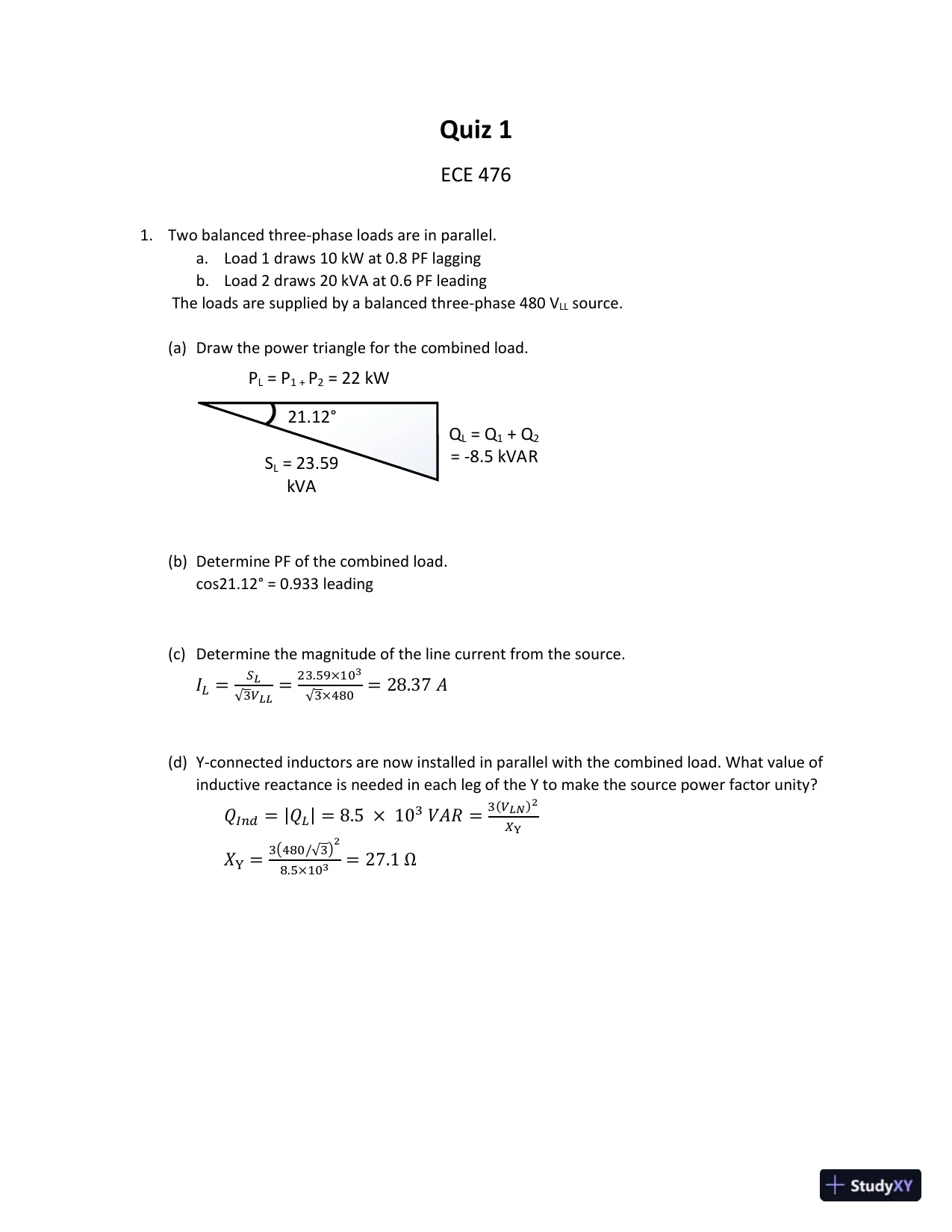
Quiz 1ECE 4761.Two balanced three-phase loads are in parallel.a.Load 1 draws 10 kW at 0.8 PF laggingb.Load 2 draws 20 kVA at 0.6 PF leadingThe loads are supplied by a balanced three-phase 480 VLLsource.(a)Draw the power triangle for the combined load.SL= 23.59kVAQL= Q1+ Q2= -8.5 kVARPL= P1 +P2= 22 kW21.12Β°(b)Determine PF of the combined load.cos21.12Β° = 0.933 leading(c)Determine the magnitude of the line current from the source.𝐼𝐿=π‘†πΏβˆš3𝑉𝐿𝐿=23.59Γ—103√3Γ—480= 28.37 𝐴(d)Y-connected inductors are now installed in parallel with the combined load. What value ofinductive reactance is needed in each leg of the Y to make the source power factor unity?𝑄𝐼𝑛𝑑= |𝑄𝐿| = 8.5 Γ— 103𝑉𝐴𝑅 =3(𝑉𝐿𝑁)2𝑋Y𝑋Y=3(480/√3)28.5Γ—103= 27.1 Ξ©

Page 2

Power System Analysis And Design, 6th Edition Test Bank - Page 2 preview image

Loading page ...

Page 3

Power System Analysis And Design, 6th Edition Test Bank - Page 3 preview image

Loading page ...

Quiz 2ECE 476Name:β€—β€—β€—β€—β€—β€—β€—β€—β€—β€—β€—β€—β€—β€—β€—β€—β€—β€—β€—β€—β€—β€—1.A 60-Hz single–phase, two-wire overhead line has solid cylindrical copper conductors with 2.4cm diameter. The conductors are arranged in a horizontal configuration with 3 m spacing.Calculate the inductance of each conductor due to both internal and external flux linkages inmH/km (40 points).𝐿π‘₯= 𝐿𝑦= 2 Γ— 10βˆ’7𝐿𝑛 (π·π‘Ÿβ€²) 𝐻/π‘šπ· = 3π‘šπ‘Ÿβ€²= 0.7788 Γ— π‘Ÿ = 0.7788 Γ— (0.0242) = 9.346 Γ— 10βˆ’3𝐿π‘₯= 𝐿𝑦= 2 Γ— 10βˆ’7𝐿𝑛 (39.346 Γ— 10βˆ’3) π»π‘š (1000π‘šπ‘˜π‘š) (1000π‘šπ»π») = 1.154 π‘šπ»/π‘˜π‘š2.The figure below is a completely transposed three-phase overhead transmission line withbundled phase conductors. All conductors have a radius of 2 cm.0.4m0.4m0.4m0.4m12m12ma.Determine the inductance per phase in mH/km (40 points).π‘Ÿβ€²= 0.7788 βˆ— 0.02 = 0.0156𝑅𝑏= √(π‘Ÿβ€²)(0.4)(0.4)(√2 Γ— 0.4)4= 0.1938π‘šπ·π‘’π‘ž= √𝐷𝐴𝐡𝐷𝐡𝐢𝐷𝐢𝐴3= √(12)(12)(24)3= 15.12π‘šπΏ = 0.2𝐿𝑛 (π·π‘’π‘žπ‘…π‘) = 0.2𝐿𝑛 ( 15.120.1938) = 0.8714 π‘šπ»/π‘˜π‘šb.Find the inductive line reactance per phase in Ξ©/km at 60 Hz(20 points).𝑋 = πœ”πΏ = 2πœ‹60 Γ— 0.8714 Γ— 10βˆ’3= 0.3285 Ξ©/π‘˜π‘š

Page 4

Power System Analysis And Design, 6th Edition Test Bank - Page 4 preview image

Loading page ...

Quiz 3ECE 476Name:β€—β€—β€—β€—β€—β€—β€—β€—β€—β€—β€—β€—β€—β€—β€—β€—β€—β€—β€—β€—β€—β€—A generator bus (slack bus) supplies a 100 MW, 50 Mvar load through a lossless transmission line withparameters on 100 MVA base below. Also, there is a 10 Mvar shunt capacitor at the load bus.X per unit: 0.2 & B per unit: 0.21.Determine the bus admittance matrix (Ybus) for the system.10 Mvar = 0.1 p.u.Assuming 1 pu bus voltage,π‘Œπ‘π‘Žπ‘=𝑆𝑉2=0.112= 0.1 𝑝. 𝑒.π‘Œ11=1𝑗0.2+ 𝑗0.22,π‘Œ12= βˆ’1𝑗0.2,π‘Œ21= βˆ’1𝑗0.2,π‘Œ22=1𝑗0.2+ 𝑗0.22+ 𝑗0.1π‘Œπ‘π‘’π‘ = [βˆ’π‘—4.9𝑗5𝑗5βˆ’π‘—4.8]2.Calculate the voltage magnitude and angle at the load bus using the Newton-Rapson method. Use theflat-start. Provide the values after 2 iterations. General power balance equations are given below.𝑃𝑖= βˆ‘|𝑉𝑖||π‘‰π‘˜|(πΊπ‘–π‘˜π‘π‘œπ‘ πœƒπ‘–π‘˜+ π΅π‘–π‘˜π‘ π‘–π‘›πœƒπ‘–π‘˜) = π‘ƒπΊπ‘–βˆ’ π‘ƒπ·π‘–π‘›π‘˜=1𝑄𝑖= βˆ‘|𝑉𝑖||π‘‰π‘˜|(πΊπ‘–π‘˜π‘ π‘–π‘›πœƒπ‘–π‘˜βˆ’ π΅π‘–π‘˜π‘π‘œπ‘ πœƒπ‘–π‘˜) = π‘„πΊπ‘–βˆ’ π‘„π·π‘–π‘›π‘˜=1𝑃2(π‘₯) = |𝑉2|(5π‘ π‘–π‘›πœƒ2) + 1 = 0𝑄2(π‘₯) = |𝑉2|(βˆ’5π‘π‘œπ‘ πœƒ2) + |𝑉2|2(4.8) + 0.5 = 0𝐽(π‘₯) = [5|𝑉2|π‘π‘œπ‘ πœƒ25π‘ π‘–π‘›πœƒ25|𝑉2|π‘ π‘–π‘›πœƒ2βˆ’5π‘π‘œπ‘ πœƒ2+ 9.6|𝑉2|]π‘₯(0)= [01],𝑓(π‘₯(0)) = [ 10.3],𝐽(π‘₯(0)) = [5004.6]π‘₯(1)= [01] βˆ’ [5004.6]βˆ’1[ 10.3] = [ βˆ’0.20.9348]𝑓(π‘₯(1)) = [0.9348 Γ— 5 sin(βˆ’0.2) + 10.9348 Γ— βˆ’5 cos(βˆ’0.2) + 0.93482(4.8) + 0.5] = [0.07140.1137]𝐽(π‘₯(1)) = [5(0.9348) cos(βˆ’0.2)5 sin(βˆ’0.2)5(0.9348) sin(βˆ’0.2)βˆ’5 cos(βˆ’0.2) + 9.6(0.9348)] = [ 4.5808βˆ’0.9933βˆ’0.92864.0737 ]

Page 5

Power System Analysis And Design, 6th Edition Test Bank - Page 5 preview image

Loading page ...

π‘₯(2)= [ βˆ’0.20.9348] βˆ’ [4.58βˆ’0.9933βˆ’0.92864.0737 ]βˆ’1[0.07140.1137] = [βˆ’0.22280.9017 ]∴ 𝑉2= 0.9017∠ βˆ’ 12.765Β°

Page 6

Power System Analysis And Design, 6th Edition Test Bank - Page 6 preview image

Loading page ...

Quiz 4ECE 476Name:β€—β€—β€—β€—β€—β€—β€—β€—β€—β€—β€—β€—β€—β€—β€—β€—β€—β€—β€—β€—β€—β€—1.A 1000-MVA 20-kV, 60-Hz three-phase generator is connected through a 1000-MVA 20-kVΞ”/138-kV Y transformer to a 138-kV circuit breaker and a 138-kV transmission line. Thegenerator reactances are𝑋𝑑′′=0.15,𝑋𝑑′=0.45 and𝑋𝑑=1.8 pu. The transformer series reactanceis 0.1 pu; transformer losses and exciting current are neglected. A 3-phase short-circuit occurson the line side of the circuit breaker when the generator is operated at rated terminalvoltage and at no-load. Determine the substransient current through the breaker in pu andin kA rms ignoring any dc offset.A.The base current on the high voltage side of the transformer is:πΌπ‘π‘Žπ‘ π‘’,𝐻𝑉=𝑆3βˆ…βˆš3𝑉𝐿𝐿=1000√3 Γ— 138 = 4.184 π‘˜π‘‰π΄πΌ" =πΈπ‘žπ‘‹π‘‘β€²β€²+ 𝑋𝑇𝑅=10.15 + 0.1 = 4 𝑝. 𝑒. = 4 Γ— 4.184 = 16.735 π‘˜π΄2.Determine Ybusin per-unit for the circuit below using a 1000 MVA system base. Per unit valuesfor the generators and transformers are given on their own base so you need to first convertsome of them to the system MVA base.G1G2500 MVA, 13.8 kVX”=0.2 pu1000 MVA, 20 kVX”=0.17 pu500 MVA13.8Ξ”/500 Y kVX=0.12 pu1000 MVA20Ξ”/500 Y kVX=0.10 puT1T2Ξ”YYΞ”500 kV LineX = 50Ξ©12Hint:𝑋𝐺1β€²β€²= 0.2 Γ—1000500= 0.4 𝑝𝑒,π‘π‘π‘Žπ‘ π‘’=π‘‰π‘π‘Žπ‘ π‘’2π‘†π‘π‘Žπ‘ π‘’=50021000= 250 Ξ©,𝑋𝑙𝑖𝑛𝑒=50250= 0.2 𝑝𝑒A.𝑋𝑇1= 0.12 Γ—1000500= 0.24 π‘π‘’π‘Œ11= βˆ’π‘— (10.4+0.24+10.2),π‘Œ12= π‘Œ21= 𝑗10.2,π‘Œ22= βˆ’π‘— (10.1+0.17+10.2)π‘Œπ‘π‘’π‘ = 𝑗 [βˆ’6.5655βˆ’8.7]

Page 7

Power System Analysis And Design, 6th Edition Test Bank - Page 7 preview image

Loading page ...

Page 8

Power System Analysis And Design, 6th Edition Test Bank - Page 8 preview image

Loading page ...

Page 9

Power System Analysis And Design, 6th Edition Test Bank - Page 9 preview image

Loading page ...

Page 10

Power System Analysis And Design, 6th Edition Test Bank - Page 10 preview image

Loading page ...

Page 11

Power System Analysis And Design, 6th Edition Test Bank - Page 11 preview image

Loading page ...

Page 12

Power System Analysis And Design, 6th Edition Test Bank - Page 12 preview image

Loading page ...

Page 13

Power System Analysis And Design, 6th Edition Test Bank - Page 13 preview image

Loading page ...

Preview Mode

This document has 40 pages. Sign in to access the full document!