

Principles and Applications of Electrical Engineering 5th Edition Solution Manual
- Electrical Engineering & Electronics
- 886 pages
- Shared May 2025
Prepare for success with Principles and Applications of Electrical Engineering 5th Edition Solution Manual, providing textbook solutions that help you understand the material better.
Preview 16 of 886 pages
See the first 16 pages exactly as they appear in the document.
Page 1 Read page 1 as text
G. Rizzoni, Principles and Applications of Electrical Engineering, 5 th Edition Problem solutions, Chapter 1 Chapter 1: Introduction to Electrical Engineering – Instructor Notes Chapter 1 is introductory in nature, establishing some rationale for studying electrical engineering methods, even though the students' primary interest may lie in other areas. The material in this chapter should be included in every syllabus, and can typically be thoroughly covered in a single-day introductory lecture. Oftentimes, reading of this material is left up to the discretion of the student. 1.1
Page 2 Page 3 Read page 3 as text
G. Rizzoni, Principles and Applications of Electrical Engineering, 5 th Edition Problem solutions, Chapter 1 Problem 1.1 Solution: A few examples are: Bathroom ventilation fan electric toothbrush hair dryer electric shaver electric heater fan Kitchen microwave fan microwave turntable mixer food processor blender coffee grinder garbage disposal ceiling fan electric clock exhaust fan refrigerator compressor dish washer Utility Room clothes washer dryer air conditioner furnace blower pump Family Room VCR drive cassette tape drive reel-to-reel tape drive record turntable drive computer fan treadmill Miscellaneous lawn tools power tools 1.2
Page 4 Read page 4 as text
G. Rizzoni, Principles and Applications of Electrical Engineering, 5 th Edition Problem solutions, Chapter 1 Problem 1.2 Solution: Several examples are listed below for each system: a) A ship Circuit Analysis design of the ship's electrical system Electromagnetics radar Solid-State Electronics radio sonar Electric Machines pump elevator Electric Power Systems lighting generators Digital Logic Circuits elevator control Computer Systems navigation Communication Systems radio telephone Electro-Optics Morse light bridge displays Instrumentation compass speed indicator Control Systems rudder HVAC b) A Commercial Passenger Aircraft Circuit Analysis Design of the plane's electrical system Electromagnetics radar microwave oven Solid-State Electronics radio Electric Machines turbines fans Electric Power Systems lighting HVAC Digital Logic Circuits seat belts Computer Systems navigation 1.3
Page 5 Read page 5 as text
G. Rizzoni, Principles and Applications of Electrical Engineering, 5 th Edition Problem solutions, Chapter 1 Communication Systems radio telephone Electro-Optics cockpit displays Instrumentation compass air speed indicator inclinometer altimeter Control Systems rudder flaps c) Household Circuit Analysis design of the home's electrical system Electromagnetics microwave oven stereo speakers Solid-State Electronics television stereo VCR Electric Machines appliances power tools fans Electric Power Systems lighting HVAC receptacles Digital Logic Circuits clocks timers Computer Systems microwave oven programmable VCR Communication Systems telephone CB radio television radio Electro-Optics digital clocks Instrumentation electric meter Control Systems thermostat 1.4
Page 6 Read page 6 as text
G. Rizzoni, Principles and Applications of Electrical Engineering, 5 th Edition Problem solutions, Chapter 1 Problem 1.3 Solution: Some examples are: a) HVAC lighting office equipment typewriter computer copy machine clock stapler shredder elevator b) conveyor punch press lighting ventilation drill press hoist lathe c) power saw drill lighting elevator pump compressor 1.5
Page 7 Read page 7 as text
G. Rizzoni, Principles and Applications of Electrical Engineering, 5 th Edition Problem solutions, Chapter 2 Chapter 2: Fundamentals of Electrical Circuits – Instructor Notes Chapter 2 develops the foundations for the first part of the book. Coverage of the entire chapter would be typical in an introductory course. The first four sections provide the basic definitions (Section 2.1) and cover Kirchoff’s Laws and the passive sign convention (Sections 2.2, 2.3 And 2.4); A special feature, Focus on Methodology: The Passive Sign Convention (p. 39) and two examples illustrate this very important topic. A second feature, that will recur throughout the first six chapters, is presented in the form of sidebars. Make The Connection: Mechanical Analog of Voltage Sources (p. 24) and Make The Connection: Hydraulic Analog of Current Sources (p. 26) present the concept of analogies between electrical and other physical domains. Sections 2.5and 2.6 introduce the i-v characteristic and the resistance element. Tables 2.1 and 2.2 on p. 45 summarize the resistivity of common materials and standard resistor values; Table 2.3 on p. 48 provides the resistance of copper wire for various gauges. The sidebar Make The Connection: Electric Circuit Analog of Hydraulic Systems – Fluid Resistance (p. 44) continues the electric-hydraulic system analogy. Finally, Sections 2.7 and 2.8 introduce some basic but important concepts related to ideal and non-ideal current sources, and measuring instruments. In the context of measuring instruments, Chapter 2 introduces a third feature of this book, the Focus on Measurements boxes, referenced in the next paragraph. The Instructor will find that although the material in Chapter 2 is quite basic, it is possible to give an applied flavor to the subject matter by emphasizing a few selected topics in the examples presented in class. In particular, a lecture could be devoted to resistance devices , including the resistive displacement transducer of Focus on Measurements: Resistive throttle position sensor (pp. 56-59), the resistance strain gauges of Focus on Measurements: Resistance strain gauges (pp. 58-59), and Focus on Measurements: The Wheatstone bridge and force measurements (pp. 59-60). The instructor wishing to gain a more in-depth understanding of resistance strain gauges will find a detailed analysis in the references 1 . Early motivation for the application of circuit analysis to problems of practical interest to the non-electrical engineer can be found in the Focus on Measurements: The Wheatstone bridge and force measurements . The Wheatstone bridge material can also serve as an introduction to a laboratory experiment on strain gauges and the measurement of force (see, for example 2 ). Finally, the material on practical measuring instruments in Section2.8b can also motivate a number of useful examples. The homework problems include a variety of practical examples, with emphasis on instrumentation. Problem 2.51 illustrates analysis related to fuses; problems 2.65 relates to wire gauges; problem 2.70 discusses the thermistor; problems 2.71 discusses moving coil meters; problems 2.79 and 2.80 illustrate calculations related to strain gauge bridges; a variety of problems related to practical measuring devices are also included in the last section. The 5 th Edition of this book includes 26 new problems; some of the 4 th Edition problems were removed, increasing the end-of-chapter problem count from 66 to 80. It has been the author's experience that providing the students with an early introduction to practical applications of electrical engineering to their own disciplines can increase the interest level in the course significantly. Learning Objectives for Chapter 2 6. Identify the principal elements of electrical circuits : nodes, loops, meshes, branches, and voltage and current sources. 7. Apply Kirchhoff’s Laws to simple electrical circuits and derive the basic circuit equations. 8. Apply the passive sign convention and compute power dissipated by circuit elements. 9. Apply the voltage and current divider laws to calculate unknown variables in simple series, parallel and series-parallel circuits. 10. Understand the rules for connecting electrical measuring instruments to electrical circuits for the measurement of voltage, current, and power. 2.1 1 E. O. Doebelin, Measurement Systems – Application and Design, 4 th Edition, McGraw-Hill, New York, 1990. 2 G. Rizzoni, A Practical Introduction to Electronic Instrumentation, 3 rd Edition, Kendall-Hunt, 1998.
Page 8 Read page 8 as text
G. Rizzoni, Principles and Applications of Electrical Engineering, 5 th Edition Problem solutions, Chapter 2 Section 2.1: Definitions Problem 2.1 Solution: Known quantities: Initial Coulombic potential energy, ; initial velocity, U V i = 17 kJ / C i = 93 M m s ; final Coulombic potential energy, . V f = 6 kJ / C Find: The change in velocity of the electron. Assumptions: ∆ PE g << ∆ PE c Analysis: Using the first law of thermodynamics, we obtain the final velocity of the electron: Q heat − W = ∆ KE + ∆ PE c + ∆ PE g + ... Heat is not applicable to a single particle. W=0 since no external forces are applied. ∆ KE = −∆ PE c 1 2 m e ( U f 2 − U i 2 ) = − Q e ( V f − V i ) U f 2 = U i 2 − 2 Q e m e ( V f − V i ) = 93 M m s ⎛ ⎝ ⎜ ⎞ ⎠ ⎟ 2 − 2 − 1.6 × 10 − 19 C ( ) 9.11 × 10 − 37 g 6 kV − 17 kV ( ) = 8.649 × 10 15 m 2 s 2 − 3.864 × 10 15 m 2 s 2 U f = 6.917 × 10 7 m s U f − U i = 93 M m s − 69.17 M m s = 23.83 M m s . 2.2
Page 9 Read page 9 as text
G. Rizzoni, Principles and Applications of Electrical Engineering, 5 th Edition Problem solutions, Chapter 2 Problem 2.2 Solution: Known quantities: MKSQ units. Find: Equivalent units of volt, ampere and ohm. Analysis: Voltage = Volt = Joule Coulomb V = J C Current = Ampere = Coulomb second a = C s Resistance = Ohm = Volt Ampere = Joule × second Coulomb 2 Ω = J ⋅ s C 2 Conductance = Siemens or Mho = Ampere Vol t = C 2 J ⋅ s Problem 2.3 Solution: Known quantities: Battery nominal rate of 100 A-h. Find: a) Charge potentially derived from the battery b) Electrons contained in that charge. Assumptions: Battery fully charged. Analysis: a) 100 A × 1 hr = 100 C s ⎛ ⎝ ⎜ ⎞ ⎠ ⎟ 1 hr ( ) 3600 s hr ⎛ ⎝ ⎜ ⎞ ⎠ ⎟ = 360000 C b) charge on electron: − 1.602 × 10 − 19 C no. of electrons = 360 × 10 3 C 1.602 × 10 − 19 C = 224.7 × 10 22 2.3
Page 10 Read page 10 as text
G. Rizzoni, Principles and Applications of Electrical Engineering, 5 th Edition Problem solutions, Chapter 2 Problem 2.4 Solution: Known quantities: Two-rate change charge cycle shown in Figure P2.4. Find: a) The charge transferred to the battery b) The energy transferred to the battery. Analysis: a) To find the charge delivered to the battery during the charge cycle, we examine the charge-current relationship: i = dq dt or dq = i ⋅ dt thus: Q = i ( t ) dt t 0 t 1 ∫ Q = 50 mAdt 0 5 hrs ∫ + 20 mAdt 5 hrs 10 hrs ∫ = 0.05 dt 0 18000 s ∫ + 0.02 dt 18000 36000 s ∫ = 900 + 360 = 1260 C b) To find the energy transferred to the battery, we examine the energy relationship p = dw dt or dw = p ( t ) dt w = p ( t ) dt t 0 t 1 ∫ = v ( t ) i ( t ) dt t 0 t 1 ∫ observing that the energy delivered to the battery is the integral of the power over the charge cycle. Thus, w = 0.05(1 + 0.75t 18000 ) dt 0 18000 ∫ + 0.02(1 + 0.25t 18000 ) dt 18000 36000 ∫ = (0.05t + 0.75 36000 t 2 ) 0 18000 + (0.02 t + 0.25 36000 t 2 ) 18000 36000 J 1732.5 = w 2.4
Page 11 Read page 11 as text
G. Rizzoni, Principles and Applications of Electrical Engineering, 5 th Edition Problem solutions, Chapter 2 Problem 2.5 Solution: Known quantities: Rated voltage of the battery; rated capacity of the battery. Find: a) The rated chemical energy stored in the battery b) The total charge that can be supplied at the rated voltage. Analysis: a) ∆ V ≡ ∆ PE c ∆ Q I = ∆ Q ∆ t Chemical energy = ∆ PE c = ∆ V ⋅ ∆ Q = ∆ V ⋅ I ⋅ ∆ t ( ) = 12 V 350 A − hr 3600 s h r = 15.12 MJ. As the battery discharges, the voltage will decrease below the rated voltage. The remaining chemical energy stored in the battery is less useful or not useful. b) is the total charge passing through the battery and gaining 12 J/C of electrical energy. ∆ Q ∆ Q = I ⋅ ∆ t = 350 a hr = 350 C s hr ⋅ 3600 s h r = 1.26 MC. Problem 2.6 Solution: Known quantities: Resistance of external circuit. Find: a) Current supplied by an ideal voltage source b) Voltage supplied by an ideal current source. Assumptions: Ideal voltage and current sources. Analysis: a) An ideal voltage source produces a constant voltage at or below its rated current. Current is determined by the power required by the external circuit (modeled as R). I V P R V I s s ⋅ = = b) An ideal current source produces a constant current at or below its rated voltage. Voltage is determined by the power demanded by the external circuit (modeled as R). V = I s ⋅ R P = V ⋅ I s A real source will overheat and, perhaps, burn up if its rated power is exceeded. 2.5
Page 12 Read page 12 as text
G. Rizzoni, Principles and Applications of Electrical Engineering, 5 th Edition Problem solutions, Chapter 2 Problem 2.7 Solution: Known quantities: Rated discharge current of the battery; rated voltage of the battery; rated discharge time of the battery. Find: a) Energy stored in the battery when fully recharging b) Energy stored in the battery after discharging Analysis: a) Energy = Power × time = 1 A ( ) 12 V ( ) 120hr ( ) 60 min hr ⎛ ⎝ ⎜ ⎞ ⎠ ⎟ 60 sec min ⎛ ⎝ ⎜ ⎞ ⎠ ⎟ J 10 5.184 = w 6 × b) Assume that 150 W is the combined power rating of both lights; then, J 10 4.32 sec 3600 ) 8 )( 150 ( w 6 used × = ⎟ ⎠ ⎞ ⎜ ⎝ ⎛ = hr hrs W J 10 864 3 × = − = used stored w w w Problem 2.8 Solution: Known quantities: Recharging current and recharging voltage Find: a) Total transferred charge b) Total transferred energy Analysis: a) C 48,600 ) (4)(60)(60 2 1 4(90)(60) ) (2)(90)(60 2 1 6(30)(60) ) (4)(30)(60 2 1 curve time - current under the area Q = + + + + = ∫ = = Idt C 48,600 = Q b) p dt dw = so ∫ ∫ = = vidt pdt w s 10800 t 00 2 7 A, t 3600 4 - 12 = i s 00 2 7 t 1800 A, t 5400 2 - 6 = i s 1800 t 0 A, t 1800 4 - 10 = i s 10800 t 0 V, t 10800 3 + 9 = v 3 2 1 ≤ ≤ ≤ ≤ ≤ ≤ ≤ ≤ 2.6
Page 13 Read page 13 as text
G. Rizzoni, Principles and Applications of Electrical Engineering, 5 th Edition Problem solutions, Chapter 2 where 3 2 1 i i i i + + = Therefore, 3 3 3 3 3 10800 7200 6 3 2 2 7200 1800 6 3 2 2 1800 0 6 3 2 2 10800 7200 3 7200 1800 2 1800 0 1 10 4 566 10 648 10 4 105 10 8 380 10 9 132 10 72 9 200 600 108 10 16 29 600 1080 60 10 86 4 100 720 90 × × + × × + × = ⎟ ⎟ ⎠ ⎞ ⎜ ⎜ ⎝ ⎛ × − − + + ⎟ ⎟ ⎠ ⎞ ⎜ ⎜ ⎝ ⎛ × − − + + ⎟ ⎟ ⎠ ⎞ ⎜ ⎜ ⎝ ⎛ × − − + = ∫ + ∫ + ∫ = . - . - . . . t t t t . t t t t . t t t t dt vi dt vi dt vi w kJ . Energy = 9 489 Problem 2.9 Solution: Known quantities: Current-time curve Find: a) Amount of charge during 1 st second b) Amount of charge for 2 to 10 seconds c) Sketch charge-time curve Analysis: a) 1 10 4 3 t i − × = Coulombs 10 2 sec amp 10 2 2 10 4 10 4 0 3 3 1 0 2 3 1 0 3 1 1 − − − − × = × = × = ∫ × = ∫ = t tdt idt Q b) The charge transferred from to t is the same as from t = 1 = 2 t = 0 to t = 1 . Q 2 = 4 × 10 − 3 C oulombs The charge transferred from to t is the same in magnitude a t = 2 = 3 nd opposite in direction to that from t = 1 to t = 2 . Q 3 = 2 × 10 − 3 Coulombs t = 4 Q 4 = 2 × 10 − 3 − 4 × 10 − 3 dt 3 4 ∫ = 2 × 10 − 3 − 4 × 10 − 3 = − 2 × 10 − 3 Coulombs t = 5,6, 7 Q 5 = − 2 × 10 − 3 + 2 × 10 − 3 4 5 ∫ dt = 0 Q 6 = 0 + 2 × 10 − 3 5 6 ∫ dt = 2 × 10 − 3 Coulombs Q 7 = 2 × 10 − 3 + 2 × 10 − 3 6 7 ∫ dt = 4 × 10 − 3 Coulombs t = 8,9,10 s Q = 4 × 10 − 3 Coulombs 2.7
Page 14 Read page 14 as text
G. Rizzoni, Principles and Applications of Electrical Engineering, 5 th Edition Problem solutions, Chapter 2 2.8 Problem 2.10 Known quantities: urve and voltage-time curve of battery recharging Total transferred energy Ana a) Solution: Current-time c Find: a) Total transferred charge b) lysis: A mA 1 . 0 100 = - time curve = Idt ∫ = 0.1 ( ) 2 ( ) 3600 ( ) + 3600 ( ) 0.1e - t-2 ( ) /0.82 dt 2 6 ∫ = 1,011 C Q = area under the current Q = 1, 011 C dw dt = P so ( ) b) ( ) ( ) ( )( ) ( ) ( ) ( ) 8,114J 0.1e 9 3600 1 . 0 1.89e 6.81 3600 3600 3600 4 2 /0.82 2 - t - 2 0 t/0.82 4 2 2 0 = ∫ + ∫ + = ∫ + ∫ = ∫ ∫ = vidt Pdt w = dt dt dt vi dt vi Ener gy = 8,114J roblem 2.11 Known quantities: urve and voltage-time curve of battery recharging Total transferred energy Ana a) P Solution: Current-time c Find: c) Total transferred charge d) lysis: A mA 04 . 0 = 40 Q = area un der the current - time curve = Idt ∫ = 0 . 04 ( ) 6 ( ) 3600 ( ) = 864 C C 64 8 = Q b) P dt dw = so . / t- - . -t/ 167 1 04 0 3 0 5 1 3600 04 0 45 0 2 1 3600 3600 00 4 2 4 0 2 2 0 4 0 4 2 2 0 = ∫ − + ∫ − = ∫ + ∫ = ( dt Pdt w 36 = ∫ ∫ = ) ( ) ( ) ( )( ) ( ) ( ) ( )( ) J , dt . e . . dt . e . . dt vi dt vi vi J , Energy 167 1 =
Page 15 Read page 15 as text
G. Rizzoni, Principles and Applications of Electrical Engineering, 5 th Edition Problem solutions, Chapter 2 2.9 Problem 2.12 Solution: Known quantities: Current-time curve and voltage-time curve of battery recharging Find: ed e ed y a 0 5t/12 = ∫ = ∫ = Idt e) Total transferr charg f) Total transferr energ Analysis: a) ( ) 12 - are Q = C 8,564 dt e 3600 curve time - current under the C 8,564 = Q dw dt = P b) so ( ) ( ) ( ) 8,986J e e 3 12 3600 2 0 5t/12 - 5t/12 - = ∫ − = ∫ ∫ = = dt vidt Pdt w Ener gy = 8,986J
Page 16 Read page 16 as text
G. Rizzoni, Principles and Applications of Electrical Engineering, 5 th Edition Problem solutions, Chapter 2 Section 2.2, 2.3 KCL, KVL Problem 2.13 Solution: Known quantities: Circuit shown in Figure P2.13 with currents I 0 = − 2 A, A, A, and voltage source I 1 = − 4 I S = 8 V S = 12 V. Find: The unknown currents. Analysis: Applying KCL to node (a) and node (b): I 0 + I 1 + I 2 = 0 I 0 + I S + I 1 - I 3 = 0 ⎧ ⎨ ⎩ ⇒ I 2 = − ( I 0 + I 1 ) = 6 A I 3 = I 0 + I S + I 1 = 2 A ⎧ ⎨ ⎪ ⎩ ⎪ Problem 2.14 Solution: Known quantities: Circuit shown in Figure P2.14. Find: The unknown currents. Analysis: Applying KCL at the node: 0 5 6 2 = + + - -i thus i = 3 A which means that a 3-A current is leaving the node. Problem 2.15 Solution: Known quantities: Circuit shown in Figure P2.15. Find: The unknown currents. Analysis: Applying KCL at the node: 0 2 5 6 = + + - i thus i = -3 A which means that a 3-A current is leaving the node. 2.10
870 more pages in the full document
Unlock it once and it stays in your library, ready to chat with or turn into flashcards.
Unlock the full documentMore Electrical Engineering & Electronics study materials
See all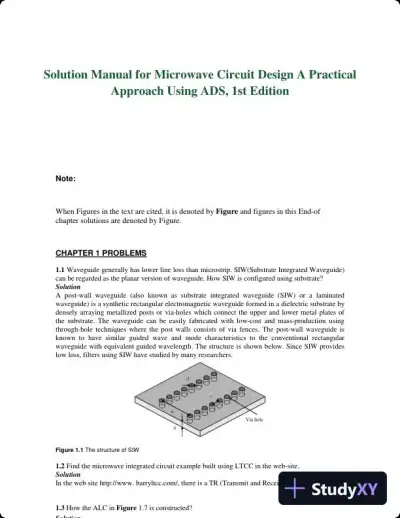 Textbook Guides
Solution Manual for Microwave Circuit Design A Practical Approach Using ADS, 1st Edition
Electrical Engineering & Electronics
121 pages154downloadsFeb 2025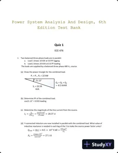 Exam Guides
Power System Analysis And Design, 6th Edition Test Bank
Electrical Engineering & Electronics
40 pages132downloadsFeb 2025 Textbook Guides
Solution Manual For Electronics Fundamentals: A Systems Approach, 1st Edition
Electrical Engineering & Electronics
278 pages93downloadsFeb 2025 Textbook Guides
Solution Manual for Fundamentals of Electromagnetics with Engineering Applications, 1st Edition
Electrical Engineering & Electronics
56 pagesMay 2025 Document
HW4_Solution
Electrical Engineering & Electronics
17 pagesFeb 2026 Class Notes
Electronic Commerce, 12th Edition Class Notes
Electrical Engineering & Electronics
196 pagesMay 2025 Textbook Guides
Electronic Commerce, 12th Edition Solution Manual
Electrical Engineering & Electronics
134 pagesMay 2025 Solved Assignments
Bridge Rectifier and its Analysis: A Study of Output Voltage and Ripple Effects
Electrical Engineering & Electronics
3 pagesMay 2025
Study this document with CramX
Once it is in your library, every tool can work from it.